
Technical Case Study: Intermittent Charging System Anomaly on a 2011 Kia Sedona EX
There is a knowledgebase article about the Intelligent Battery Sensor and why you don’t “hook anything up on the ground post” and only to chassis ground. It can save you lots of time, money, and headache: https://techbravo.net/knowledgebase/the-modern-battery-guide-understanding-the-ibs. If you want to see my headaches… keep reading!
This technical case study details the advanced diagnosis of a persistent, intermittent charging system failure and stalling anomaly on a 2011 Kia Sedona EX (3.5L V6). After multiple failed alternator and battery replacements, the focus shifts to finding elusive high-resistance faults in terminations, grounds, and control relays. The guide outlines a precise diagnostic strategy utilizing a Thermal Imaging camera and specialized electrical testing to pinpoint the true cause of the chronic electrical failure.
HERE IS THE SERVICE MANUAL I REFERENCED: https://techbravo.net/2011-Sedona-SVC-Manual/index.html
My test equipment includes, but is not limited to, an ANCEL BA101 Car Battery Tester, an ANCEL AD310 OBDII Scanner, a Tektronix THS720A Oscilloscope/True RMS Multimeter, and a URPRO IR Thermal Imaging Camera.
Part I: Vehicle Specifications and Failure History
This section documents the vehicle details and the chronic, recurring nature of the electrical failure.
Vehicle Technical Specifications
| Feature | Specification | Notes |
| Model/Trim | 2011 Kia Sedona EX | Full-size minivan platform. |
| Engine | 3.5L DOHC 24-valve V6 (Lambda II G6DC family) | Shared platform with various Hyundai/Kia models. |
| Mileage | Approx. 138,000 miles | Trouble-free for the first 138k miles. |
| Alternator Rating | 150 A | The original equipment is internally regulated and typically communicates with the ECM. |
| Charging Control | ECM-controlled (likely PWM or LIN/BSS protocol) | The Engine Control Module manages alternator output based on system voltage and battery sensor input. |
| High-Current Protection | Relies on high-amperage bolt-in Multi-Fuses and dedicated relays. | Located in the Engine Compartment Fuse/Relay Box. |
Observed Failure History (Last 3 Months)
The vehicle has exhibited a classic intermittent charging failure followed by a system shutdown.
| Event | Action Taken | Failure Behavior |
| 1st Issue | Replaced battery and alternator. Alternator replacement article here. | Driving normally, dash indicators (Battery, TPMS, Airbag) flashed, with the Battery Light coming on first and remaining steady. Vehicle eventually stalled. |
| 2nd Issue | Checked battery/alternator (tested OK), deep-cleaned all terminals, removed a high-draw aftermarket sound system (rated up to 200A max draw). | Same behavior: Battery light, multiple indicator flashes, drove ~5 miles until stalling. |
| 3rd Issue | Checked battery (OK), Replaced Alternator (again). | After driving normally for a period, the exact same stalling behavior recurred. |
| Current Status | 4 tow bills, 3 alternators, 1 battery, stereo delete, and lots of time and trouble later, the issue persists. | The van sits due to the intermittent, recurring anomaly—a sudden, complete charging system failure and stall. |
Conclusion from History: The repetitive nature of the failure, despite multiple component replacements, strongly suggests a persistent, high-resistance fault in the wiring, a critical relay/contactor, etc…
Note: After consulting the OEM wiring diagram for the charging system, it looks like the ECM controls the alternator output based on the input from the battery sensor. The charging circuit from the alternator output to the battery is pretty straightforward and beyond the cable terminations, has a fuse inline. The battery sensor is peripheral and not in series with the main charging positive cable. The battery current sensor could still be faulty and is integrated into the negative battery terminal assembly.
I do remember the dash ‘going crazy’ as the failure would manifest itself. It looked like ECM/Ground issues, etc… but I dismissed the ECM since it would drive ‘normal’ again and I associated it to the instability of the vehicle electrical system in general.
Part II: Advanced Diagnostic Plan
The diagnostic plan is structured to move past component replacement and target any intermittent electrical failure points—the high-resistance terminations, grounds, and control components, etc… and check everything up to a possible ECM issue. We will also check for the main fuse, the battery sensor, and the related wiring and terminations.
Phase A: High-Priority Thermal Imaging (TI) Inspection Protocol
Using a thermal camera is the ideal method to find a high-resistance fault, as the anomaly will appear as a “hot spot” under load.
| Step | Rationale | Critical Targets for Inspection |
| 1. Cold Soak & Load | Maximizes the temperature differential to make high-resistance visible. | Start from cold. Activate Max Load (High Beams, HVAC blower on High, Rear Defrost). |
| 2. Scan Positive Path | The highest current flows between the alternator and the battery. | Alternator B+ Post and cable lug; Engine Bay Distribution Block terminals; Battery Terminal Clamps (looking at the crimp behind the post). |
| 3. Scan Ground Path | High resistance on the negative side is the most common cause of systemic electrical failure. | Engine Block Ground Strap (Battery to Engine); Chassis Ground Points (Battery/Engine to Frame/Fender). Battery sensor (ground battery terminal integration) |
| 4. Scan High-Current Relays | Relay contacts or their sockets act as high-current “contactors.” | MAIN RELAY (ECM Power) in the Engine Bay Fuse Box. Scan the relay body and the plastic fuse box socket for heat. |
Phase B: Electrical and Component Verification
These tests verify the health of the high-current components that are typically not visible.
| Component Group | Check Method | Acceptance Criteria / Action |
| Main Alternator Fuse/Link | Voltage Drop Test (Engine Running, Full Load) across the bolt-in Multi-Fuse (e.g., 150A) in the engine box. | Must be <0.05 Volts DC @ 50 mV. A higher reading means internal resistance failure. |
| Main Relays (ECM Power) | Relay Swap Test with the MAIN RELAY and other critical Ignition Relays (IG1/IG2). | Swapping with an identical, known-good relay eliminates intermittent internal contact failure. |
| Alternator Control Wires | Wiggle Test on the small wire harness plug at the alternator. | Monitor charging voltage while gently wiggling the harness to check for intermittent signal loss to the ECM. |
| Battery Current & Temp Sensor | Inspection of the sensor located on the negative battery cable and testing per the service manual. | Ensure clean, secure connection and proper operation. A faulty signal here disrupts the ECM’s ability to command charging. |
If all of this ‘checks out’ then I will revisit the ECM as a possible cause, but I’m starting to suspect the battery current sensor more and more.
Part III: The Root Cause: The Intelligent Battery Sensor (IBS)
My investigation concludes that the erratic dashboard behavior and stalling were rooted in the failure of the Intelligent Battery Sensor (IBS)—a precision component integrated into the negative battery cable assembly. Following the replacement of this assembly, the vehicle’s charging profile has stabilized, confirming that the original sensor had either drifted out of calibration, suffered internal hardware degradation, and or was damaged by incorrect jumpstarting, charging, etc.. The aftermarket sound system has been ruled out as a direct contributing factor, but more care will be used in the future to match high-current equipment more closely to the power it has ‘on hand’. UPDATE: This didn’t fix it either! See more below.
💥 1. Why the Sensor Fails: The Surge Factor
The IBS is a sensitive low-side shunt resistor. Its purpose is to monitor voltage, current, and temperature, allowing the ECM to vary alternator output for fuel efficiency. However, its position makes it vulnerable to:
-
Jump Packs & Boosters: High-powered lithium or lead-acid jump packs can deliver between 400A and 2000A. If these are clamped directly to the negative battery post, that massive surge flows through the IBS. This can desolder internal components or “drift” the shunt’s resistance, leading the ECM to receive corrupted data (e.g., seeing 12.6V as 10.5V).
-
High-Current Aftermarket Equipment: Equipment such as audio amplifiers, hydraulic pumps, and air-ride compressors create significant electrical stress. If these are grounded incorrectly, they create two distinct failure modes:
-
The “Blind” Load: Grounding high-draw equipment directly to the negative battery post “hides” the load from the IBS. The computer remains unaware of the drain, leading to chronic undercharging.
-
Inductive Kickback: High-current motors (like hydraulic pumps) create voltage spikes when they cycle off. These spikes can “noise out” the LIN-bus communication between the IBS and the ECM.
-
🔌 2. Correct Grounding Architecture
To maintain system stability on IBS-equipped vehicles, a strict grounding hierarchy must be followed:
-
Jump-Starting/Charging: Always connect the negative lead to a chassis ground or engine bolt. Never touch the negative battery post directly.
-
High-Draw Accessories: Ground all aftermarket amps and pumps to the chassis frame. This ensures the return current flows through the IBS, allowing the ECM to “see” the demand and increase alternator output to compensate.
🛠️ 3. Final Diagnostic & Reset Protocol (2-Wire Variant)
If you have replaced the negative cable or battery, or if the system is acting erratically after a jump-start, follow this verification for the 2-pin connector:
IBS Connector Pin-Out
| Pin | Function | Expected Value |
| 1 | Power Supply (B+) | 12V Constant (Check dedicated fuse) |
| 2 | Signal Output | Variable Voltage or PWM (Typically 0.5V–4.5V) |
Note: In 2-wire setups, the sensor often grounds itself through the battery post connection, using the two wires for power and data transmission to the ECM.
The “Deep Sleep” Relearn
The system requires a calibration period to “map” new hardware. After installation:
-
Turn off all accessories, remove the key, and lock the vehicle.
-
Do not disturb for 4 hours. 3. The IBS will measure the Open Circuit Voltage (OCV) in “Deep Sleep” to recalibrate its State of Charge (SoC) markers.
With the new negative cable assembly and a proper 4-hour relearn period, the Sedona is now maintaining a steady 13.5V to 14.7V charging range. By ensuring all aftermarket high-current grounds are routed through the chassis and avoiding direct post-boosting, we have eliminated the “cascading light” phenomenon and restored the integrity of the charging system.
Technical Note: In the modern “Smart Alternator” era, the negative battery post is no longer just a terminal—it is a data-collection point. Treat it with the same care as you would a delicate engine sensor.
Part IV: NOPE, Didn’t Fix It!
It died again, and I had it towed again (not to the river, back to the house).
However, I did a new search for the issue and found this gem of a video!
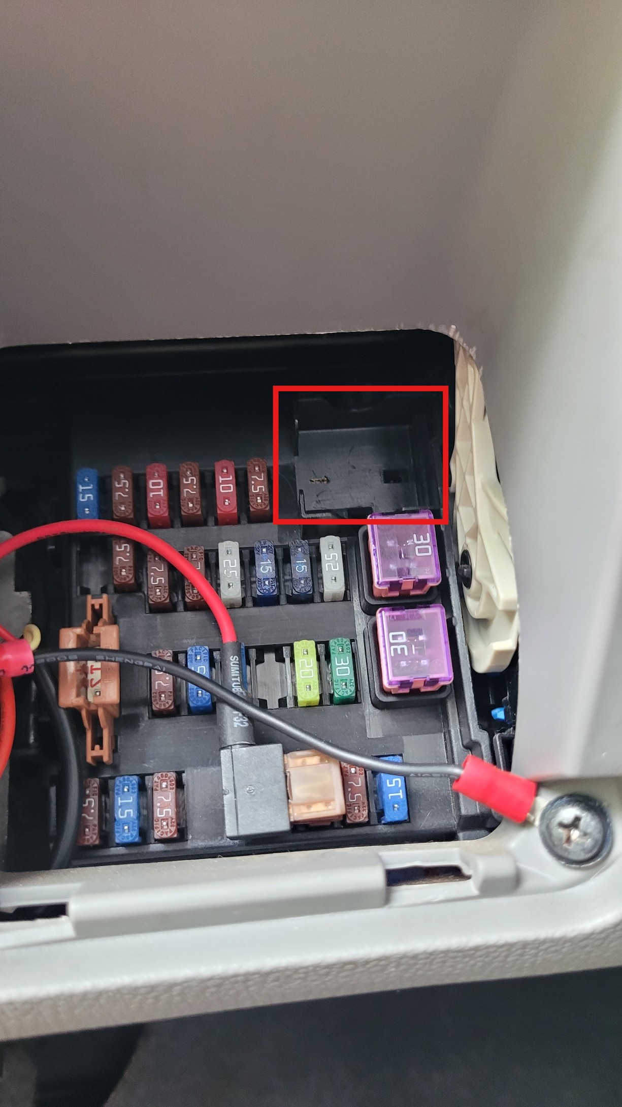
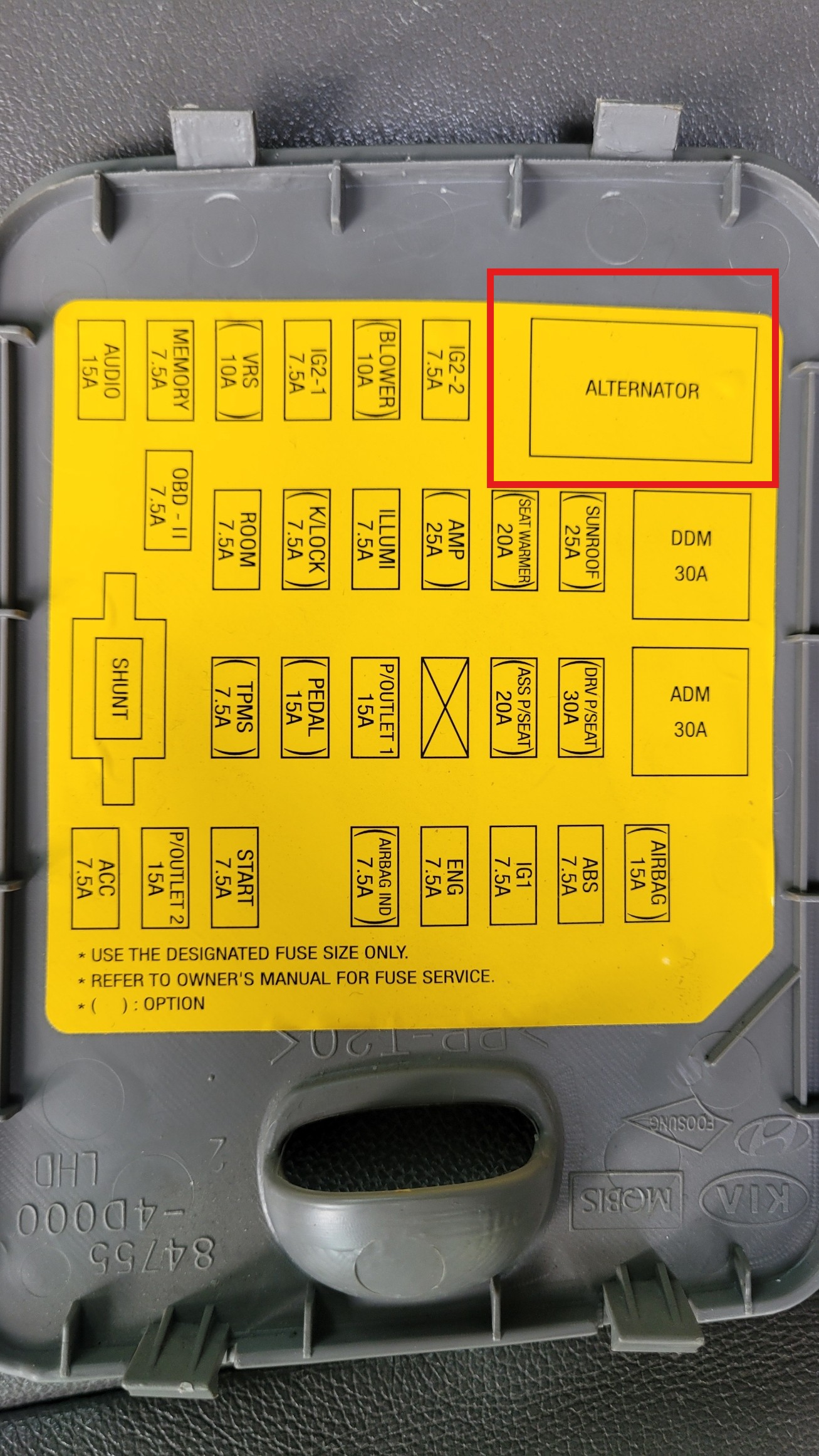
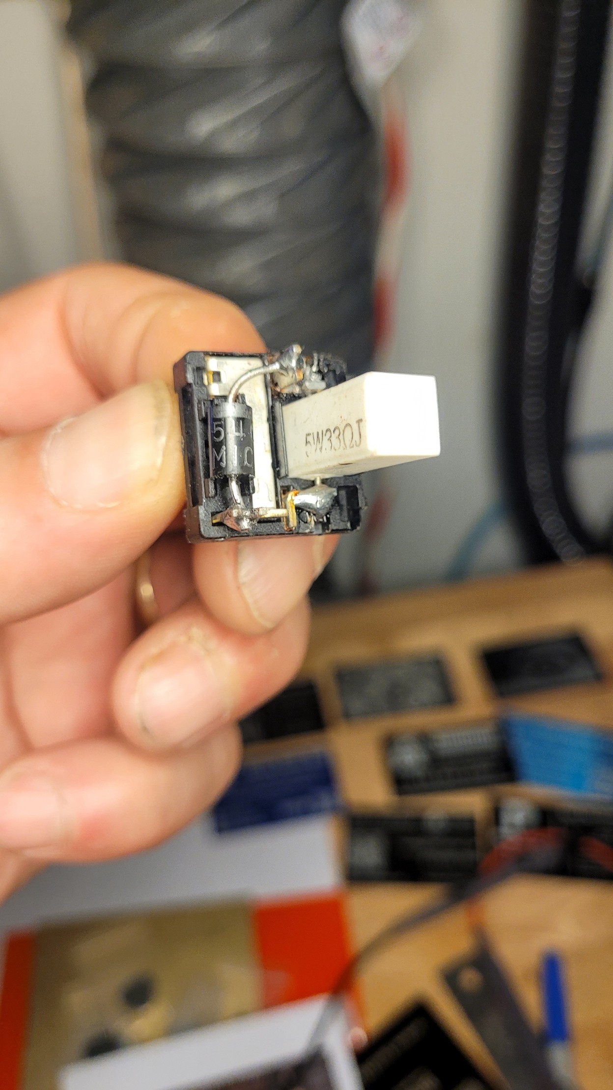
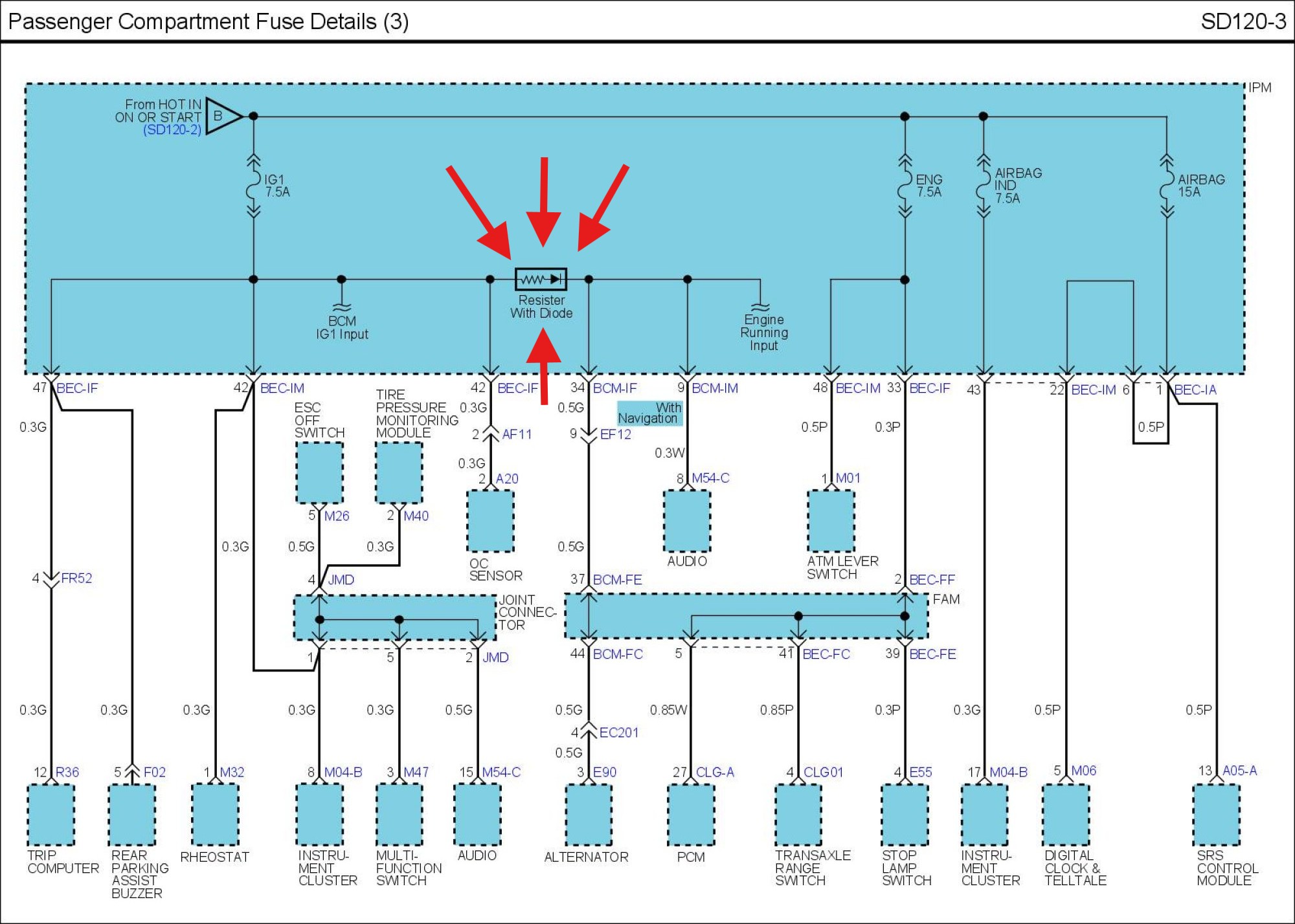
And sure enough my resistor read 33 ohms but my diode was bad!, it would not forward bias on diode test and showed open in both directions on this mystery part. So I had a pack of diodes in hours (thanks amazon!) and replaced it. I haven’t tested it yet, I’m kind of scared of it after all this… and i don’t care to ever require the services of another wrecker LOL.
Here is my ‘Mystery Kia Part’ taken apart before diode replacement

We will give the battery a full charge and lend it to a friend for a long trip for the final test… Not, but I will keep you posted.
Part V: STILL NOPE, Still Didn’t Fix It!
Now I’m reading again that aftermarket alternators for this vehicle often wont work and that an OEM alternator has fixed it. So now I’m contemplating yet another alternator replacement. Everything else has been checked and/or replaced at least once. The ECM has not been eliminated as the cause either.
Now What? Here is What I Found
1. The Aftermarket Alternator Voltage Regulator Issue
-
- Why it happens: The engine control module (ECM) communicates directly with the alternator’s internal voltage regulator using a pulse-width modulated (PWM) duty signal. [1, 2]
- The failure mode: Many aftermarket voltage regulators use a “generic” internal chip that cannot interpret Kia’s specific ECM data frequency. The alternator sits completely dormant because it is waiting for a command signal it doesn’t recognize. [1]
- The fix: Many mechanics find that only a genuine OEM Hyundai/Kia alternator (or a premium rebuild using an original Denso/Valeo core) will successfully communicate with the car’s computer and activate charging. [1]
A new OEM alternator from Kia is $860+.
2. The Aftermarket Battery Current Sensor Conflict
-
- The diagnostic test: Unplug the small electrical connector attached to that aftermarket battery sensor completely. [1]
- What this does: When the ECM loses signal from the battery current sensor, it triggers a built-in safety default. It ignores smart charging protocols and forces the alternator to put out a flat, continuous 13.8V to 14.2V. [1, 2]
- The result: If you unplug the sensor, start the van, and it suddenly begins charging, your aftermarket sensor is either defective or sending inaccurate voltage/amperage profiles to the computer.
A new OEM Ground Cable/Battery sensor assembly from Kia is over $300.
3. The Mystery Box
4. A Fractured LIN/FR Control Wire
- Unplug the small harness plug on the back of the alternator. [1]
- Inspect the terminal pins inside the plug for green copper corrosion or loose terminal tension (pins that have stretched open and aren’t snugly grabbing the alternator blades).
- Check for a broken wire inside the insulation roughly 3 to 6 inches back from the alternator plug where the harness flexes during engine torque.
4. I’m Getting Rid of The Van
Here is the Facebook Marketplace Ad: https://www.facebook.com/marketplace/item/1734517994242116