BLW-LITA.v1 Linear Table User Guide
Overview
The Bravo Laserworks (BLW) LITA (Linear Integrated Table Assembly) was specifically designed to function with the Thunder Laser Aurora v2 T-Slot bed option factory rotary port but can be adapted for use on just about any galvo laser with a rotary port and typical bed, optical plate, etc… with a LightBurn compatible controller.
It also can work in a V1 Aurora but to get more of the workspace some modifications to the laser housings are required. more on that here: Taking A Hacksaw To My Aurora 8 v1.0
This equipment is intended to be a simple, economical, light-duty motorized table with flexible use cases.
Things You Will Need
- A Galvo Fiber/UV Laser Engraver with compatible rotary port
- An M3 hex wrench to secure the 4 plate mounting screws
Important Safety Information
- This device is motorized and can activate autonomously causing damage, injury, fire, death, etc… This is basically a death machine, so treat it accordingly.
- Always de-energize the equipment completely before attempting any maintenance, adjustment, or repair.
- Do not become pinched or otherwise entrapped in the mechanisms.
- Do not wear loose clothing, ties, coats, long sleeves, jewelry, etc… while attempting any maintenance, adjustment, or repair.
- Do not modify, alter, or otherwise operate this equipment beyond its intended purpose and limitations.
- For motor and laser compatibility queries, please consult with Bravo Laserworks Support and the laser OEM Support
Included Components
Raw Indexing Table
The diagram is for information only, not for manufacturing.
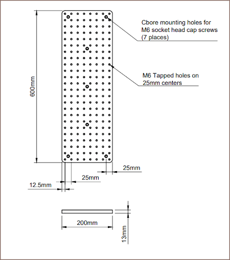
Item/Drawing is subject to change without notification.
The hole pattern for mounting the plate to the gantry is specified in the Gantry Mounting Template section in this guide. The drilling of these mounting holes is performed in-house.
Linear Actuator
The linear actuator comes pre-assembled and ready to run. This is the part breakdown for the linear actuator assembly:
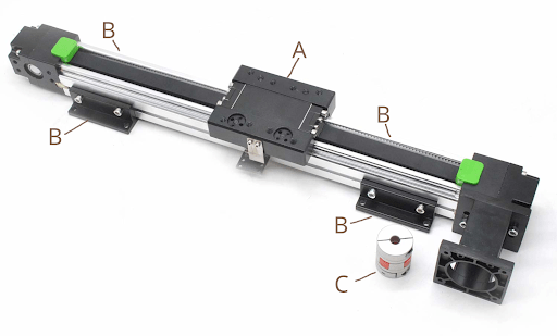
| REF | QTY | DESCRIPTION |
| A | 1 | Bearing Plate |
| B | 4 | Mounting Brackets (NOT USED) |
| C | 1 | 8mm Motor Flex Coupling |
| D | 1 | Nema 23 Closed-Loop Hybrid Motor Driver (NOT SHOWN) |
| E | 1 | 7 Pin XLR Motor Cable – THUNDER V2 (NOT SHOWN) |
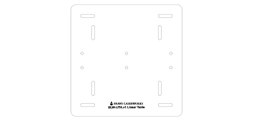
Acrylic Base
The acrylic comes pre-attached to the linear actuator drive unit and uses the base mounting hardware to secure the unit to your galvo laser bed.
Base Mounting Hardware
This hardware is used to secure the base plate to the Laser Galvo bed.
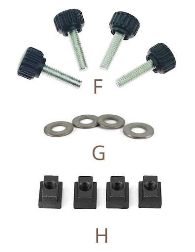
| REF | QTY | DESCRIPTION |
| F | 4 | M6 Thumb Screws |
| G | 4 | M6 Flat Washers |
| H | 4 | M6 T-Slot Nuts |
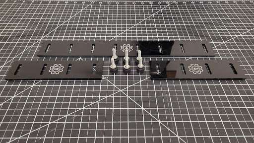
Basic Guide Kit
The basic guide kit is included with the table. The kit includes 2 short guides and 1 long guide as well as 6 thumb screws with washers. The guides are acrylic so take care not to break them.
You can make your own specific to your needs and we could offer consulting services and assist.
We also plan to develop more fixtures, jigs, mounts, guides, etc… from other materials and designs as we move forward.
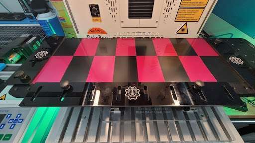
Here is an example of the basic guides in use to batch 16 standard aluminum business cards:
Assembly & Fitment
Assembling The Table
The unit comes almost fully assembled. We leave the relatively heavy optical plate removed so it doesn’t stress the bearing plate assembly and bearings.
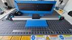
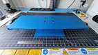
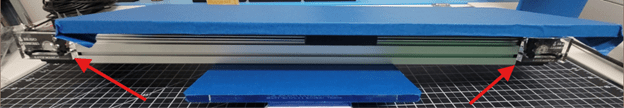
You need to carefully remove 3 plastic cable ties marked ‘Remove Carefully’ (red arrows).
The gantry spacer (green arrow) goes on the top of the gantry plate (orange arrow).
Then the optical plate (blue arrow, shown still wrapped) goes on top of the spacer.
Then install four flat-head hex screws (yellow arrow) to secure the plate and spacer.
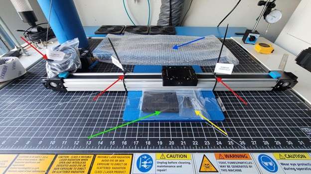
NOTE: You may want to mount the linear actuator, and then install the optical plate to get easy access to the rear mounting bracket anchoring position(s). See Fitment below.
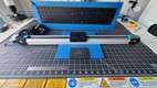
Here is the table at each stage mentioned above:
 |
 |
 |
 |
| Before spacer fitment | After spacer fitment | Place table on top | Secure with 4 screws |
Fitment To Laser
The unit comes with M6 mounting hardware and T-Nuts as mentioned in the Included Components section above, so you can use this table on most galvo laser drilled and tapped optical plates with M6 holes 25mm on center as well as T-Slot beds with 8mm wide X 4mm deep slots.
Basically center up the linear table on the laser bed and secure each mounting flange with 1 anchor point with the included hardware. The thumbscrews are intentionally long so the stop nuts will allow you to use the hardware in shallow threads, etc…
You may need to reposition a bit or make more adjustments in the Setup & Calibration section coming up next, just FYI.
Setup & Calibration
Duplicating Profiles
The settings in this manual are nominal values and some tuning may be necessary.
NOTE: You will need to make duplicate device profiles from your known good profile. One for batch marking, and one for continuous marking.
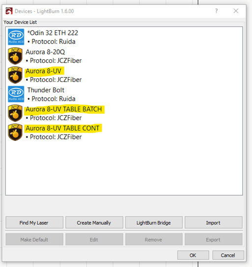
You can find more on duplicating device profiles here:
Changing a Galvo Lens – LightBurn Documentation
Batch Marking (Repeat Marking)
Nominal External Axis Repat Marking Setup
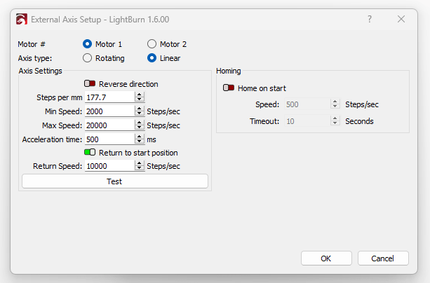
The steps per mm is calculated by dividing the stepper driver resolution setting (12800) by the distance traveled with one revolution (this linear table moves 72mm with one pulley revolution). So in the case of this v1 table:
12,800 / 72 = 177.77
You must disable the Start Marking port in the LightBurn Device Settings for the Batch Device Profile to prevent the foot switch, etc… from interfering with this process.
Continuous Marking (Rotary Split Marking)
Nominal Chuck Rotary Setup for Continuous Marking:
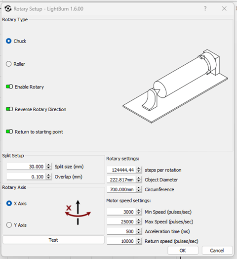
The steps per rotation is calculated by dividing the total range of motion (500 or 700mm, depending on the build) of the table by the distance traveled with one revolution (72) and then multiplying that by the motor resolution (12800). So in the case of this v1 table:
500mm linear actuator(500 / 72) * 12,800 = 88,888.89
(700 / 72) * 12,800 = 124,444.44
You must disable the Start Marking port in the LightBurn Device Settings for the Batch Device Profile to prevent the foot switch, etc… from interfering with this process.
Setting Up The Workspace in Lightburn
See existing Lightburn resources. More is coming soon.
General Usage
The intended purpose of this table is to be a platform for acrylic, wood, etc… base plates, guides, jigs, fixtures, etc… or can be fitted with sticky mats, etc… possibly.
At the most basic level, some substrate could be used to prevent marking and marring the table surface. Then place the objects evenly using registration marks, guides, drawn outlines, etc… laid out on the insert.
Batch Marking (Repeat Marking)
See existing resources here: https://docs.lightburnsoftware.com/latest/Reference/RepeatMarking or email support@techbravo.net for assistance..
Continuous Marking (Rotary Split Marking)
See existing resources or email support@techbravo.net for assistance.
Advanced Usage
Using a base plate as described above with indexing holes, joints, etc… to jig and fixture your specific product can be the best approach.
Bravo Laserworks is exploring the idea of providing some fixtures for common items.
Maintenance & Care
Please email support@techbravo.net for assistance.
Troubleshooting
Please email support@techbravo.net for assistance.
Technical Specifications
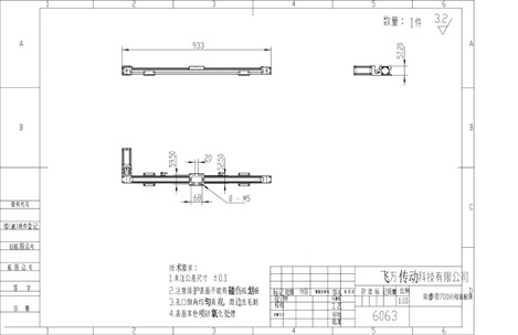
Linear Actuator
This is the drawing of the 500mm Linear Actuator Assembly:
Gantry Plate Mounting Template
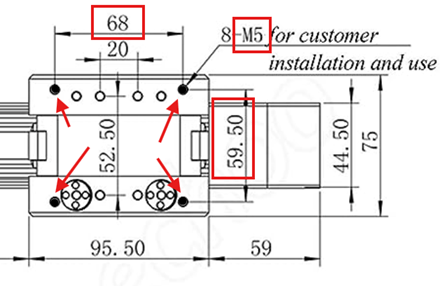
Table Assembly
Motor/Driver Variants (Thunder Specific)
NOTE: This integrated hybrid stepper/driver can be made to work on most lasers with no internal driver for the rotary port. And you can adapt it with the correct motor to work on most lasers with no internal driver for the rotary port.
Model:JSS57P2N
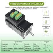
Type: Hybrid
Encoder Resolution: 1000
Motor length: 57x57x76mm
Shaft Diameter: 8mm
Total length: 107mm
Power: DC24-48V; Current: 4.2A
Model: Leadshine iST-2309
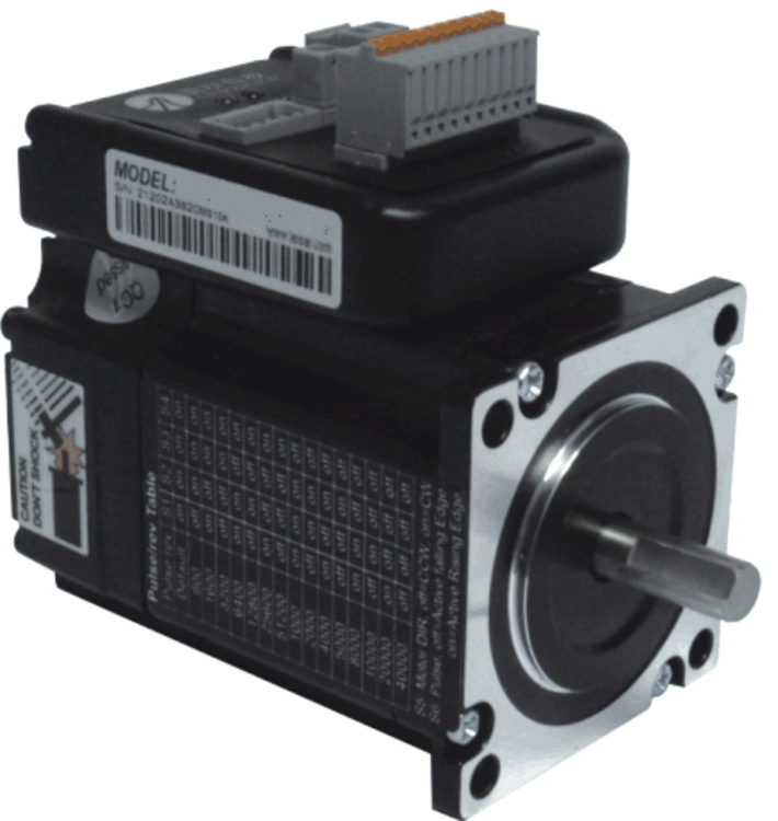
Type: Hybrid
Encoder Resolution:1000
Motor length:57x57x76mm
Shaft Diameter:8mm
Total length:107mm
Power: DC24-48V; Current:4.2A
DIP Switch Config
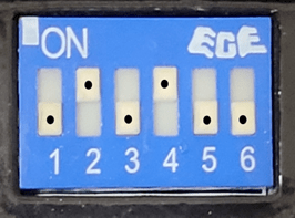
| 1 | OFF |
| 2 | ON |
| 3 | OFF |
| 4 | ON |
| 5 | OFF |
| 6 | OFF |
Aurora v2 Motor Wiring & Variations
Aurora v2 Motor/Driver Pinout
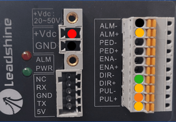 |
⦿ 1 | +36Vdc |
| ⦿ 2 | GND | |
| ⦿ 3 | PUL- | |
| ⦿ 4 | DIR- | |
| ⦿ 5 | DIR+(+5Vdc) | |
| ⦿ 5 | DIR+(+5Vdc) | |
| ⦿ 5 | ALM+(+5Vdc) | |
| ⦿ 0 | ALM- |
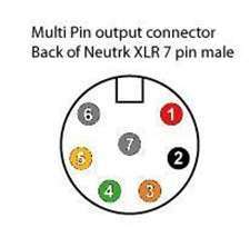
Aurora v2 Rotary Port Pinout
 |
⦿ 1 | +36v DC PWR |
| ⦿ 2 | GND DC PWR | |
| ⦿ 3 | XPUL- | |
| ⦿ 4 | XDIR- | |
| ⦿ 5 | LOGIC +5VDC | |
| ⦿ 6 | JUMPERED TO 7 | |
| ⦿ 7 | JUMPERED TO 6 |
Aurora v1 Motor Wiring & Variations
Aurora v1 Motor/Driver Pinout
 |
⦿ 1 | +36Vdc |
| ⦿ 2 | GND | |
| ⦿ 3 | PUL- | |
| ⦿ 4 | DIR- | |
| ⦿ 5 | DIR+(+5Vdc) | |
| ⦿ 5 | DIR+(+5Vdc) | |
| ⦿ 5 | ALM+(+5Vdc) | |
| ⦿ 0 | ALM- |
Aurora v1 Rotary Port Pinout
 |
⦿ 1 | +36v DC PWR |
| ⦿ 2 | GND DC PWR | |
| ⦿ 3 | XPUL- | |
| ⦿ 4 | XDIR- | |
| ⦿ 5 | LOGIC +5VDC | |
| ⦿ 6 | JUMPERED TO 7 | |
| ⦿ 7 | JUMPERED TO 6 |
Other Specs
Thunder Aurora v2 Working Area per Lens
The table dimensions for the LITA v1 are based on the information below assuming a max static work area of 200mm x 200mm:
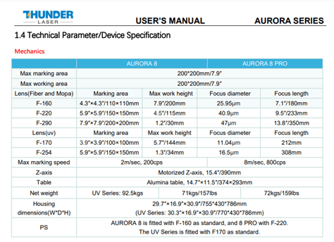
NOTE: The height from laser base to the linear table exceeds the focal limitations of some of the wider lenses. Please see the table specs.
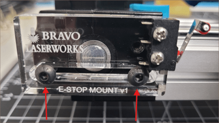
End-Stop Switches (Optional, and dependent on each use case.)
This linear table has a rudimentary but effective electro-mechanical end-stop switch system to help prevent damage from overtravel, etc… and can sometimes be interfaced with some lasers.
This system employs the existing Alarm I/O on the integral Motor/Driver and two microswitches, one on each end of the linear actuator. It does not report positioning to the laser controller, it simply ‘kills the motor’ if either switch is actuated.
To recover after an endstop trigger, move the table away from the switch and then remove/restore power to the motor by removing and reinserting the rotary connector from the port, cycling power on the machine, pressing the e-stop then pressing ON again (for Thunder Aurora v2), etc…
These endstop switches may need to be adjusted if not working properly. You can loosen the 2 screws fixing the endstop mount and slide to adjust
Limited OEM Warranty
We warrant the equipment to be free of manufacturing defects or component failure for 90 days.
Obtaining Support
Bravo Laserworks Provides only remote support and assistance.
- Monday – Friday: 6pm to 9pm Central
- Saturday: 9am to 5pm Central
- Sunday: Closed
Our mode of support is our ticketing system via email.
Please email support@techbravo.net for assistance.
