Circuit & Safety Wiring
The most critical step now is the wiring. We need to complete the Blumlein circuit and, most importantly, prepare the wiring for the Safety that makes this kit more suitable for classrooms, etc…
 Triple-Threat Safety Imperative: READ THIS FIRST
THIS PROJECT INVOLVES THREE DISTINCT LETHAL/HARMFUL HAZARDS. DO NOT ATTEMPT REPLICATION WITHOUT ADVANCED HIGH-VOLTAGE EXPERIENCE AND PROPER VENTILATION.
- 1.
 Lethal High Voltage: The
  circuit is lethal. NEVER touch the circuit when power is applied. All components must be contained within a grounded, non-conductive enclosure with safety interlocks before operation.
 - 2.
 Harmful UV Radiation: The laser emits deep ultraviolet (
 ) light (around
  ). This radiation is invisible, damaging to the retina, and can cause skin burns. NEVER look into the beam or at the spark without certified UV-blocking eye protection.
 - 3.
 Toxic Ozone Production: The high-energy discharge generates ozone (
 ) gas (a toxic air pollutant). Operation must be limited to short bursts and always performed in a well-ventilated area or under forced exhaust.
Classroom Use: Replication in any educational setting requires direct, professional supervision and a fully interlocked safety enclosure system.
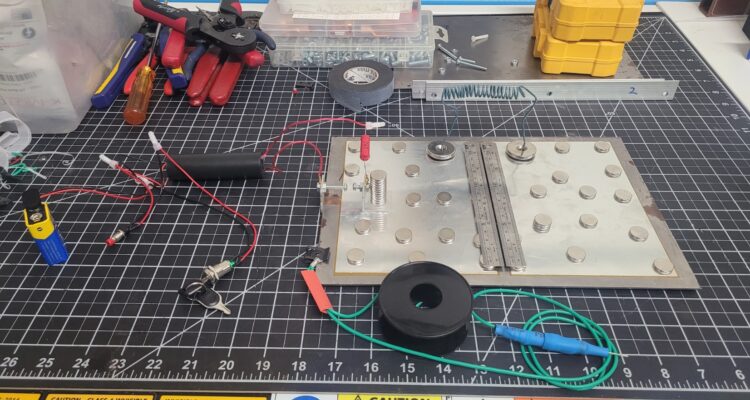
⚡ Wiring the Nanosecond Pulse
The low-inductance Blumlein principle demands the shortest, widest conductors possible.
-
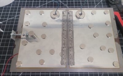
HV Connections: I’m using wide flat contact points whenever possible for all 10 kV discharge connections (Capacitor
 to SG, SG to
  ). This minimizes inductance and ensures the pulse fires fast. We may have to play with connections and terminations a bit during debugging.
 -
Circuit Path: The current flows through the terminals, charges the plates, and when the SG fires, the pulse flows instantly across the 6 inch laser channel.
⚠️ Adding Mandatory Safety Resistors
Based on best practices for high-voltage systems, we are including two critical resistor components:
-
Charging Resistor (
 ): A
): A  HV resistor is wired in series with the 10 kV supply. This limits the initial current surge into the
  capacitor, protecting the power supply and dampening noise.
 -
Bleed Resistor (
 ): A HV resistor is wired in parallel across the main capacitor plates ( to ). This is a critical safety component that automatically drains the lethal residual charge when the power is turned off.
🔒 Mandatory Safety Wiring
To make the final product safe, most primary controls are mounted on the enclosure panel and wired internally:
-
Interlock Wiring: The firing circuit is routed through a connector for the Microswitch Interlock. If the viewing lid is removed, the laser cannot fire.
-
Key Switch & Single or Dual Button Wiring: The low-voltage input power for the 10 kV supply is wired internally through the panel-mounted Key Switch and the Dual-Button Simultaneous Fire controls, enforcing safer ‘class 1 like’ operation.
Here is the functional schematic of the circuit
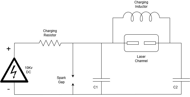
⚡ Complete N2 TEA Laser Schematic
The circuit is based on the Blumlein Transmission Line configuration, which is designed to produce a voltage pulse that is twice the charging voltage with an extremely fast rise time, which is essential for exciting the nitrogen gas to lase at  .
.
| Component | Value/Rating | Function in the Circuit | |
| HV PSU |  DC DC |
Power source that charges the capacitor bank. | |
| Charging Resistor |  |
SAFETY/CONTROL: Limits inrush current to protect the HV PSU. | |
| Capacitor 1 (Storage) |  |
Stores the primary high-voltage energy. | |
| Capacitor 2 (Switching) | |
Provides the grounded side of the discharge path (uses the Iron Base Plate). | |
| Bleed Resistor | |
CRITICAL SAFETY: Automatically discharges the residual, lethal charge in C1 and C2 when the power is off (This item is not shown in the diagram). | |
| Spark Gap | Adjustable ( to to  ) ) |
The high-speed switch. Fires automatically when the voltage is sufficient, initiating the nanosecond pulse. | |
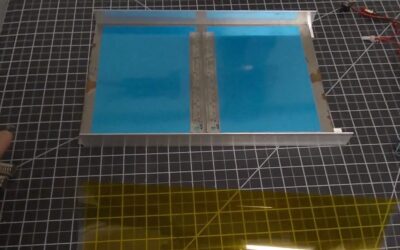
| Laser Channel |  |
The pair of N2 electrodes (steel rulers) where the laser action occurs. |
Blumlein Operation Summary
-
Charging: The
 charges through to
  . remains near ground potential as it is tied to the grounded Iron Base Plate.
 -
Firing: When
reaches the breakdown voltage of the  , the SG fires, creating a short circuit from to .
 -
Pulse Generation: This sudden transition causes a high-voltage pulse (a ‘traveling wave’) to race across the laser channel. Since the Blumlein line effectively adds the voltage of the charged line to the voltage of the adjacent line, the instantaneous voltage across the laser channel peaks at
 (twice the charging voltage).
 -
Lasing: This
 pulse is delivered with a sub-
 rise time, which is fast enough to excite the
  gas in the surrounding air and create the UV laser beam. Introducing Nitrogen gas to the laser channel would result in far better results, but for the purpose at hand, that’s not necessary.
Metering The Connections
After checking the resistance at key connection/termination points, I have determined that the laser channel and inductor connections will need to be improved. The other points, magnetically fixed included, were very good.
Stay tuned for Part 5 where I get a final assembly for v1 and button everything up enough to power up and debug/tune!