Serving Middle TN for over 20 yrs.

Fill out the form below to get your free initial consult

    📩 Contact Tech Bravo

    Complete the form below and we'll get back to you shortly.


    Serving Middle TN for over 20 yrs.

    N2 TEA Laser Build – Part 4: Circuit & Safety Wiring

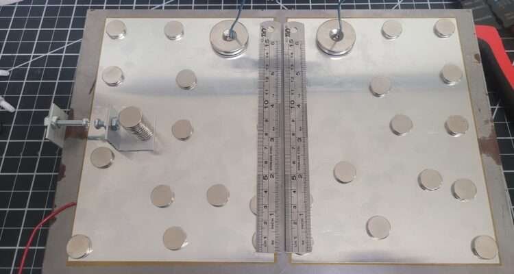
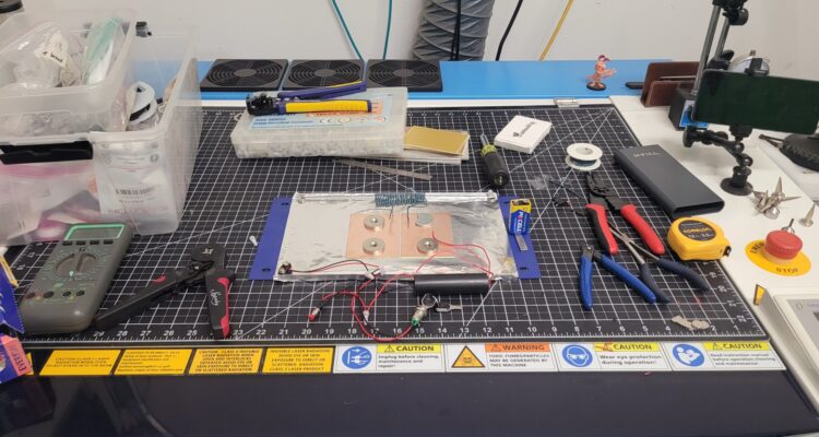
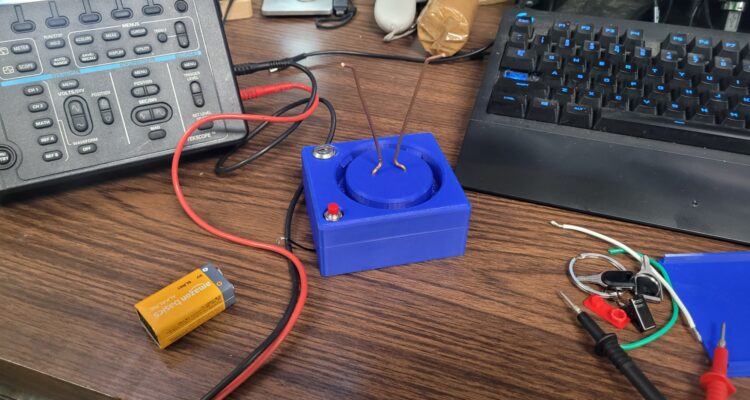
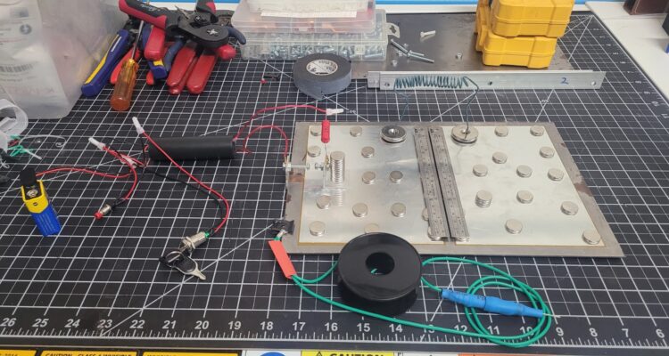
    Circuit & Safety Wiring. The most critical step now is the wiring. We need to complete the Blumlein circuit and, most importantly, prepare the wiring for the Safety that makes this kit more suitable for classrooms, etc… Triple-Threat Safety Imperative: READ THIS FIRSTTHIS PROJECT INVOLVES THREE DISTINCT LETHAL/HARMFUL HAZARDS. DO NOT ATTEMPT REPLICATION WITHOUT ADVANCED HIGH-VOLTAGE EXPERIENCE AND PROPER VENTILATION.1.  Lethal High Voltage: The  circuit is lethal. NEVER touch the circuit when power is applied. All components must be contained within a grounded, non-conductive enclosure with safety interlocks before operation.2.  Harmful UV Radiation: The laser emits deep ultraviolet () light (around ). This radiation is invisible, damaging to the retina, and can cause skin burns. NEVER look into the beam or at the spark without certified UV-blocking eye protection.3.  Toxic Ozone Production: The high-energy discharge generates ozone () gas (a toxic air pollutant). Operation must be limited to short bursts and always performed in a well-ventilated area or under forced exhaust. Classroom Use: Replication in any educational setting requires direct, professional supervision and a fully interlocked safety enclosure system.

    N2 TEA Laser Build – Part 2: The 10 kV Concept

    N2 TEA Laser Build – Part 2: The 10 kV Concept – Okay, I’m ready to pull back the curtain! I’m building a Nitrogen (N2) TEA (Transversely Excited Atmospheric) Laser. This is a high-performance physics experiment that relies on a single principle: speed. We use 10,000V to create an electrical pulse so fast it tricks the nitrogen gas (present in the open air, in this case) into emitting an invisible UV laser beam.. More here: https://techbravo.net/n2-tea-laser-build-part-2-the-10-kv-concept/

    N2 TEA Laser Build – Part 1: What Is That?

    The workbench is getting weird this week. (Yes, that’s my Thunder Laser engraver, I know, I know—it’s not supposed to be a workbench! 😅) This is the first in a series of posts where I break down the science and build a ‘Trophy-Worthy’ high-voltage device. I’ve got steel, copper, aluminum, magnets, switches, some wiring, etc..—but I’m actually building something that combines advanced physics, high-voltage power (10,000 V), and lasers! The goal is to harness the fastest electrical pulse a human can create in the lab to generate a powerful ultraviolet beam. This thing is cool and you will either walk out of school with a science trophy in your hand, or in handcuffs, depending on what day you bring it in 🤪… so always check with your school or organization before taking a science project like this to school, etc…! STAY TUNED!!! #PhysicsFun #HighVoltage #DIYElectronics #Lasers #PulsedPower #WhatsThis  

    Reviving a Vintage Alarm with Meshtastic – Part 1: The Plan

    When my family and I moved into our new house, we found a legacy DSC Alarm Panel and its suite of wireless sensors already installed. Since the system was outdated, unmonitored, and completely disconnected from modern alert systems, I opted to remove it. However, the hardware itself—a testament to its vintage engineering—was robust and still functional. I decided that instead of tossing it, I would transform this robust, inherited system. This multi-part series isn’t just about cleaning up an old alarm; it’s about transforming it into an off-grid, resilient, and intelligent security guardian using the Meshtastic mesh networking protocol! My ultimate goal is to create a fully self-reliant, peer-to-peer notification system that can alert me even when the internet is down, power is out, or cellular networks are jammed. I am taking this abandoned, time-tested wireless DSC system and giving it a powerful, modern, digital voice.

    President Dwight D. CB Base Resto-Mod Part 3

    🔬 Part 3: Documentation and Cleanup Complete – The Final Blueprint (This post directly follows the investigative findings detailed in President Dwight D. CB Base Resto-Mod Part 2.) This post marks a crucial phase transition! We executed the Initial Restoration (Cleaning) and the rigorous Technical Investigation (Data Collection) using the equivalent schematics. We now have the definitive blueprint showing the nature and intent of the modifications, but the final confirmation of function awaits the test bench in Part 4. The need for component replacement will be determined only after exhaustive initial performance tests. 1. 🧹 Step One: Initial Restoration and Deep Clean Before trusting our visual inspection or beginning the technical research, stabilization was necessary. This initial phase was purely physical cleaning—no components were removed, replaced, or adjusted. Deep Cleaning the Base Station Dust Removal: We used compressed air and soft brushes to carefully remove the thick, accumulated dust and grime from the main PCB, heat sinks, and chassis interior. This simple act drastically improved component visibility. Chassis and Controls: The exterior chassis, faceplate, and knobs received a thorough wipe-down with mild cleaners. Results: The cleaning was a success! We now have clear sight lines across the entire board, making the wiring easier to trace.   2. 📖 Step Two: Technical Investigation and Functional Analysis 🗺️ Using documentation for the equivalent PC-198AB chassis, we performed a side-by-side analysis of the schematics against the physical wiring. This gave us the necessary insight to understand the function and purpose of the mods, which we will now validate with testing. The Cobra 29XLR used 2 boards. The main one was a PC-198AA and the other was a PC-241AB 1/2. Looks like most of the docs for the XL29 with PC-198AA. This should give us some clarity. Cobra 29XLR Owner Manual Cobra 29XLR OEM Schematic Cobra 29XLR SVC MAN Schematic Cobra 29XLR Service Manual The Four Highly Probable Modifications We Now Identify: Mod # Hypothesis Purpose & Next Step (Validation) A Frequency Expansion PURPOSE CONFIRMED: Wiring alters the PLL’s BCD pins for extended channel selection. VALIDATION: Part 4 will confirm if the bands are stable and correctly programmed. B Clarifier Track PURPOSE CONFIRMED: The disc capacitors stabilize the TX/RX frequency track in the VCO circuit. VALIDATION: Part 4 will test if the transmit frequency follows the receive frequency across the sweep. C Variable Power PURPOSE CONFIRMED: Wiring intercepts the Automatic Power Control (APC) circuit. VALIDATION: Part 4 will confirm if the repurposed knob controls RF output power. D Audio/Modulation Tweak PURPOSE CONFIRMED: Wires/soldering in the AMC circuit suggest the limiter is bypassed. VALIDATION: Part 4 will measure the modulation percentage to confirm if it swings beyond stock limits. The Repurposed Switch Solved! We successfully traced the wires for the Channel Expansion mod (Mod A) and found they lead to the Noise Blanker (NB) switch. We now know which factory function was sacrificed, ready for functional testing. 3. 🎬 What’s Next: The Testing Phase The investigation is complete, and we have the full restoration blueprint. Now, we prepare for the physical work and the critical validation step. Part 4 will involve the rigorous performance testing of the currently configured radio, after replacing the failing peripherals (cords, jack). This testing will be the final step to CONFIRM the functionality of all four mods. The decision to install newer components, remove mods, or keep the rig “as is” will be made only after testing reveals a failure or performance shortfall. We are sticking to the mantra: Document, Test, and Only Then Decide to Replace.

    President Dwight D. CB Base Resto-Mod Part 2

    🔬 Part 2: Cracking the Case – Board ID, PLL, and Hidden Mods! You can find President Dwight D. CB Base Resto-Mod Part 1 here. The moment of truth arrived! I cracked open the President Dwight D. base station, ready to confirm the board type and uncover the history hidden beneath its metal shell. This radio had clearly seen some enthusiastic use—and definitely some meticulous user-installed modifications. 1. Board ID: Confirmed PC-198AB Chassis The first priority was identification. I quickly confirmed the board version: it’s the classic PC-198AB chassis, distinguished by its use of the well-known Uniden D858 PLL chip! This chip and board combination immediately told me something important: this specific rig was from the era of radios highly favored by enthusiasts for modifications. 2. A Modder’s History: Three Core Findings This radio was definitely not stock! The moment the lid came off, it was clear a previous owner had a serious interest in getting more performance and functionality out of the rig. I found evidence of three major, non-factory interventions: Mod A: Channel Expansion (The PLL Wiring) 📈 This is the most visually obvious and complex modification. It dramatically extends the radio’s frequency capability. Evidence: Multiple colored wires (green, blue, yellow, and brown) are soldered to the pins of the D858 PLL chip, and a large resistor bridges two adjacent points. Hypothesis: This is the classic technique used to alter the PLL’s digital programming code, enabling the radio to access expanded channels (often referred to as “upper” and “lower” bands) outside of the standard 40 CB channels. Next Step: I strongly suspect those two green wires visible near the PLL are running to the front panel, having repurposed the Noise Blanker and or CB/PA switches to control the band switching. Tracing this will be critical in Part 3! Mod B: Unlocked Clarifier (TX/RX Track) – Capacitor Tweak 🔗 Flipping the board over revealed a precise adjustment made near the frequency control circuits. Evidence: Two distinct disc capacitors (identifiable by their shape and insulation) are hand-soldered across two points on the foil side of the board in the Clarifier (Delta Tune) circuit area. These are user-installed components, not factory parts. Hypothesis: This setup enables the Clarifier Unlocked (TX/RX Track) feature. The capacitors are strategically placed to tailor the frequency response of the Voltage Controlled Oscillator (VCO), ensuring the transmit frequency tracks the receive frequency consistently as the Clarifier knob is adjusted. This is a crucial mod for talking to others on those expanded channels. Mod C: Modulation/Audio Circuit Tweak 🔊 More non-factory wiring was found near the rear of the board, suggesting a focus on audio performance. Evidence: Several additional, loose wires (red, white, and black) are hand-soldered to the foil side of the board in the area where the main factory harness connects. This spot is typically near the Automatic Modulation Control (AMC) and audio circuits. Hypothesis: This is likely an attempt to enhance the modulation (make the audio louder/punchier) by tweaking the gain or modifying the modulation limiter to achieve greater swing on the air. 🎬 What’s Next: The Road Ahead The President Dwight D. is turning out to be a fascinating piece of radio history! It was clearly a highly customized workhorse. My next steps for Part 3 will be to clean up the unit and dust it all off and tidy it all up after a close visual inspection. Then verify reference service manuals, diagrams, schematics, etc… to officially confirm the switch repurposing, and to clarify which suspected mods are in fact mods or repairs. I will decide later which of these modifications to preserve or remove in the interest of stability and clean performance, check and replace any suspect caps, and/or begin the critical restoration of the classic Astatic D-104 TUP9 microphone. For now I’m going to get it all figured out and working. More to follow! Here are more pics:

    President Dwight D. CB Base Resto-Mod Part 1

    🎙️ Resurrection of a Classic: President Dwight D. CB Base & Astatic D-104 TUP9 Resto-Mod! Stoked to finally crack open my President Dwight D. CB Base Station! This rig, a decade-long resident of the garage, fired right up a few years ago and was technically working. Now it’s time for a proper restoration and revitalization to ensure this classic rig lasts! My plan focuses on preservation, performance, and a critical deep-dive into its legendary companion, the Astatic D-104 Power Mic on the TUP9 stand. 🔎 Phase 1: Internal Inspection & Component Audit Before replacing any parts, I need to know the radio’s precise configuration and history of modifications. This is crucial for future component sourcing and tuning. Board Identification: The President Dwight D. came with two main boards. I’ll open it up to identify the Phase-Locked Loop (PLL) chip: PC198AA Board: Uses the AN-858-PLA U PD858 PLL. PC 407 Board: Uses the U PD2816 PLL. Modifications Check: I’ll be looking for any evidence of “Super Mods,” specifically if the clarifier has been clipped or if any modulation tuning has been performed. Capacitor & Resistor Inspection: I’m taking the “don’t fix it if it ain’t broke” approach with a major exception: vintage electrolytic capacitors degrade over time. I’ll be inspecting and selectively replacing these key components for long-term stability and optimal audio coupling. 🎤 Phase 2: The Astatic D-104 TUP9 Resto-Mod The Astatic D-104 on a TUP9 base is an iconic combination that deserves the full restoration treatment. 1. Cleaning and Maintenance Deep Clean: A thorough cleaning of the mic head, chrome, and the heavy TUP9 base to remove years of dust and grime. Contact Cleaning: The Push-To-Talk (PTT) bar mechanism and the volume potentiometers (pots) inside the TUP9 stand will be cleaned with high-quality contact cleaner (like DeoxIT). This is essential to eliminate static, scratchy audio, and intermittent keying. 2. Cord Replacement & Wiring The old microphone cord will be replaced with a new, high-quality cable. Crucial Step: The new cord must be correctly wired to mate the D-104 (Audio, Ground, TX/PTT, RX) with the President Dwight D.’s mic jack (in this case a 4 pin GX16 aviation connector). Getting the pinout right is essential for it to key up and transmit audio properly! 3. Performance Upgrades (“Resto-Mod” IF required) Amplifier Board Upgrade: The internal pre-amp board in the TUP9 is a common point of failure or weak performance. I may replace the vintage board with a modern, low-noise amplifier kit tailored for the TUP9 base to provide cleaner, more punchy modulation. RF Filtering: D-104s are notorious for picking up stray RF (Radio Frequency) energy. I will check for and potentially install a small, simple RF suppression network (capacitor/resistor) on the audio line to keep the signal clean. 🛠️ Phase 3: Final Tune-Up & Reassembly With the internal components secured and the D-104 revitalized, the final steps will bring the entire base station back to peak condition. Task Detail Pots & Switches Clean all remaining potentiometers and switches in the radio (RF gain, volume, squelch, channel selector). Cord Replacement Replace the old, stiff power cord (not just the mic cord!) for safety and a fresh feel. Alignment I will check the radio’s frequency and perform a basic tune-up and alignment to maximize its transmitted power and receive sensitivity, ensuring it’s right on-frequency. Wish me luck on this fantastic project! I’ll be posting updates on the board type, any mods I find, and the transformation of this classic rig!  You can find President Dwight D. CB Base Resto-Mod Part 2 HERE.

    Taking A Hacksaw To My Aurora 8 v1.0

    So. I’m burning the midnight oil and burning up a few hacksaw blades and cutting up the Aurora a little bit to give a little more clearance. This V1 housing had this and I made a linear table for the V2 and it works on this one, but it sits too far forward. So I’m making that so I can slide it back. the full use of the workspace. I decided to use just a hacksaw and a small drill bit to perforate some material at specific locations. It was the least invasive, least noisy, least messy strategy. I didn’t want to run a grinder or dremel and all that. i’ll dress up those edges and it will look almost like it was meant to be. More on setup and use to follow. https://www.youtube.com/shorts/0JF78CIRTbw?feature=share https://www.youtube.com/shorts/0JF78CIRTbw?feature=share Okay, so I cut the sides out of the Aurora and I cut some rudimentary guides out of some stuff I got from Houston acrylic. Ice blue mirror. It’s beautiful and it looks pretty on my linear table and it stinks to high heaven when you cut it. It’s terrible.  My daughter had some furniture with wobbly legs and we discovered that they had these little feet them so I ordered a bunch on Amazon and gave her what she needed and kept the rest. And lo and behold, they’re perfect to hold my guides in place on here. They’re low profile. I can tighten them up with a quarter or a screwdriver back edge of a knife or whatnot. Just thought that was cool. I’ll keep you posted. More to follow. Okay, so I’ve got the guides on. I’ve got 10 cards loaded. I’m using uh batch repeat marking actually in LightBurn. So basically it’ll allow me to load 10 cards on here. I could load up to 16 the way I have it, if I configured a little bit differently. I’m just going to do 10 at a time. So now I can let it do 10 cards at once automatically and not have to babysit the machine. So finish this one and move to the next one and go all the way to the end. Pretty cool. https://www.youtube.com/shorts/0JF78CIRTbw?feature=share

    The Big AM Radio Watch

    I was in my dad’s workshop the other day and I saw this big watch and was curious about it. He said take it… so I took it apart, cleaned everything, and put it back together. It is in remarkably good condition aside from a small hairline crack in the dial at about 7 o’clock which is barely distinguishable.  The case is in great condition sans some minor patina, which is to be expected. The buckle has a bit more, but is still very good. I was even able to use 3 of the original plastic bushings for the strap pins, and small section of 5mm PVC tubing i had lying about was an almost perfect match to the originals.  The bezel has some minor scratches and blemishes but is in pretty good shape. And the bezel spins even with the retaining screws fully engaged, so there is some very slight scuffing on the dial. But its not visible with the bezel fitted. I soldered the speaker wires (this thing even has an earphone jack on the back) and popped in a fresh 9 volt. With some twisting and pushing of the on/off/volume knob (Pot) and a bit of tuning… I had voices, but it sounded horrible.   So, I took it back apart and cleaned the pot and variable tuning cap to clean up the audio and looked for any solder points, etc… that are suspect and tried again for some good, clear audio.

    Soltron Electronic PCB VR Replacement

    This ia a Soltron Electronic III Display PCB from an Ergoline Soltron Chill XL70 Tanning Bed. This board has obvious thermal defects to the L5973D voltage regulator IC as well as to the trace and the board. It is rumored that this particular board is plagued with this particular issue. The entire board new is likely $800~$1000 and used ones can go for $400~700.   Here is some imagery of the affected component:           These ICs are surface mount and are soldered on the underside. Without a decent hot air soldering station, flux, solder paste, etc… you could botch the repair. Since the original chip was toast anyway, i poured the heat to it with a touch of flux and removed it. It takes patience (as well magnification in my case) but it’s not too bad, you just have to be careful not to overheat any surrounding components, etc… Then i cleaned up the pads and traces (except for the one that was not a charred crevasse in the board), applied solder paste to the clean pads, then a touch of flux and the chip settled into place (after 5 solid minutes of nudging and shifting and heating). Once it was tacked into place a made sure i had good flow everywhere, then used a single strand of some 14~12 AWG stranded and made a good repair between the leg of the IC and the pad. Here is the 1st try. It probably would have been okay… but I reworked those areas. Here is it again after rework: This board will be field tested and I will update this as needed. UPDATE: That did not fix the board. Back to board-level diag… We will keep you posted.

    Overhauling My Old Benchmade AutoStryker

    So I’ve been carrying a Benchmade Auto Stryker for decades now, and it was pretty beat up when I got it.. So I decided to use the fiber laser and sandpaper, etc… to clean it all up as much as i can then finish it up on the buffing wheels. I just popped the knife in the fiber galvo laser and fired off what I thought would be a good series of passes to clean coatings and ‘other stuff’ off of the knife as much as possible without disassembly. I did however remove the pocket clip and put it and the screws in a parts baggie. Then tried the handle. And I did the blade, and removed the OEM branding, but thats okay, I’ll engrave it back in the proper place when I’m done. Then I buffed on the knife a bit with scotch brite pads, steel wool, and got the Dremel in some difficult spots. Then I wanted to clean it all up, inside and out. So I opted to clean it with an ultrasonic cleaner instead of taking it apart. I’ve had that and similar knives apart before… but if it ain’t broke, don’t fix it… I put the knife in the cleaner with water and after 180 seconds there was not much difference. So i dumped the water and used 100% LA’s Totally Awesome (an awesome complex surfactant) and the yuck started oozing out as soon as the unit was turned on. And I put the logo back on the blade:       MORE TO FOLLOW…

    Thunder Odin Telemetry Project

    I came across Node-RED and wanted to see some of what it could do, so I plan on outfitting my Thunder Odin 32-60 with all kinds of sensors so I can monitor and interact with the laser in real-time. Then maybe I’ll explore what else it can do. I’ll update my progress here as time allows.    

    The Drawing Machine

    So I was looking at some 3D prints that the gradkid may like. I had some SG90 servos and various microcontroller/developer boards and I found this awesome design. I have most everything I need on hand, so this is perfect. And my grandson had seen this somewhere before and loves it. The designer has all kinds of cool stuff, check him out: @matixovi Here is the link to the project I followed: https://makerworld.com/en/models/978425-scara-2d-drawing-robot-esp32-five-bar-link This is what the drawing machine essentially is: Click the image to see the animation I’m making this one all white and using chrome/silver hardware, as that’s what i have in stock. Here is my print: And the machine with the servos mounted: MORE TO FOLLOW

    Fist Attempt At Making Some T-Shirts

    in my attempt at my very first project, i accidentally made all 13 t-shirts in just a few hours. they are likely not perfectly centered or uniform, and i haven’t fully tested the washability/durability yet. but i was pleased with the initial results. i was expecting the first real batch to take 2 days and quite a few failures to complete. i was pleasantly surprised at how smooth it was. printing the designs was easy and i married all the prints first, then went back and pressed all the designs on the shirts. i didn’t take a pic of the completed shirts yet but i do have this short rambling overview of the project:  

    The Flamethrower

    Intro Okay so this isn’t actually laser related (though I could add a red dot pointer to it i suppose!) but it involves high voltage, fire, and more… so the boys and I are going to build a flamethrower. We will go over legalities and use cases as well as best practices of design, build, and use with an emphasis on safety and risk management. I looked at many similar devices, both commercially available and DIY, as well as data on the military equipment. I opted for the fuel pump over having a pressurized tank of ‘gas’ strapped to my back. Those high pressure systems require careful engineering and design to be safe. The system I’m building uses gravity to get the fuel to the pump and it’s only pressurized from the pump outlet to the nozzle. Additionally I will likely have normally closed solenoids both immediately after the fuel tank outlet as well as immediately before the nozzle. If this fuel pump type device goes well, I may try a pressurized tank system in the future… Parts List This will be function over form and likely a crude build initially so bare-bones as far parts go. Here is the parts list so far: External Universal Inline Electric Fuel Pump 12vDC 60KV High Voltage Generator Module Ceramic Electrode Ignition Plug Auxiliary Fuel Tank (1L with Vent) Mini Momentary Push Button Switch 6-6000 Brass Sprayer Cone Nozzle 1/8″ Brass Mini Ball Valve 1/8″ NPT Brass Nipple 2″ Length 1/8 NPT to Male Metric M12 x 1.5mm Adapter Rechargeable 12V 3250mAh Battery Pack 1/8″ Solenoid Valve Normally Closed (2) Various Wire Ties Various Adhesives Various fuse holders, connectors, ferrules, etc… 16AWG stranded 100% copper power wire Various Tools Various Fire Suppression Equipment Various PPE for High-Voltage, flash burns, eye protection, etc… and more Proof of Concept Here is a short video of the main components temporarily fabricated and having power applied for 10 seconds or less to test and get proof of concept: Okay so this first build is just a test fixture so I can test and debug, the final version may or may not be housed inside a hard case, briefcase, etc…  

    The 4 Axis CNC Machining Center

    I picked up this Intelitek Expert Mill VMC-0600 with 4 axes, automatic tool changer, pneumatically actuated collet chuck, mister, touch probing, tool probing, mix and max limit switches on x, y, and z axes… and it runs a Beaglebones based Acorn board and CNC12 control software. I have experience with 3 axis gantry lasers, 3D printers, Vinyl Cutters, Inkjet & Laser printers, etc… but i’m 3 days into machining, so cut me some slack LOL. Also please point out anything I messed up, missed, or could improve on. I appreciate all feedback.  I’ll update this post as I move along.   Auto Tool Changer & Auto Probing Overview    Using The Touch Probe To Index A Wax Block I realize after more digging that I can probe material all sorts of ways and possibly even create profiles/ digitize parts, at least to some degree without buying additional tiers/licenses. I will be doing a full X/Y/Z probing on the block next.   I found a video that helped me immensely. I am going to watch it 2 more times, double-check my soft travel limits and probe calibration, then I’ll spin it up and try not to crash it. Here is the video that gave me lots of clarity:   It’s WD-40 I know of other/better coolants/lubricants… and I know about fire risks and all that, but I plan to run wd-40 in my mister for some things. I’ve been asked about it (the contents of that bottle) a few times, so i’ve labeled the container ‘accordingly’ for clarification…  

    The TXC UV Wall Printer

    This is a UV printer that prints on walls. I thought it was some cool tech and I wanted to learn more about one, so I traded one of my many hardly-used lasers for one.   I’ve had experience with wide/large format inkjet printers but none that printed vertically, and not specifically UV, but it looks pretty simple (I’m sure its not ‘that simple’) and familiar so off I go… This is the overview of the drive systems. This model uses belts, not the rack and pinion that I’ve recently seen on the newer units. https://youtu.be/8is8VmAjmm0 Reported Model Number Discrepancy According to the seller, (who had factory reps remote in to setup & train him) and all the markings, documentation, etc… it’s a TXC-UV900. But the frame and peripherals are different in a few places. The visual identification suggests that it’s a TXC-WP390. I’ve dealt with Chinese OEM’s and it could be an early version of the uv900. There is some intermingling of upgrades/updates in the manufacturing process as they have to use up the old stock first and they deplete at different stages, at least to some degree. Some Initial Testing i mean who wouldn’t want a haphazardly placed, mostly complete, almost life-size print of Reba’s head on their wall? I’ve Made Some Progress The manual says you need Photoshop to add a spot color for white on the CMYK channels. Gimp won’t do it. So I fired up Corel-Photo Paint 2018 and I am able to add spot color channel for white as well as define/import color profiles for the printer. So I think that’s where I’ll do most of my prep, hopefully using templates and other assets in the editor. Then I can bring it into the RIP or maybe send it directly to the buffer since the color profiles are dialed in. There is an OEM video of adding the white spot color in Photoshop here. My Aim is to replicate that in Corel Photo-Paint.   UPDATE: I did accomplish the exact same thing for the alpha channel in Corel Photo-Paint. The Wall Printer Has Been Sold I successfully printed with it, learned to calibrate, purge, maintain, focus, etc… the printer but it had to go so we could reclaim our front room. I decided I didn’t want to start a wall printing business. So I moved it before it sat around and dried up. On to the next one!

    Thunder Bolt Head Camera

    I had originally tested LightBurn’s Head Mount camera function on my Thunder Nova 35-80 and never got to test it fully. This was early on and was the v1.2 beta, more info on that implementation can be found in this Thunder Laser USA Knowledgebase Article: Head Mounted LightBurn Camera.   So I figured since LightBurn public release was at v1.7.01, I’d run a head cam on my Thunder Bolt and see if I could get it going.   I Designed a simple mount in Fusion and printed it on my Bambu P1S (after some recalibration and tweaking). Here is the calibration attempt.  

    The Thunder Mug

    The thundermug is an Enerpac RC256 25 Ton 10,000 psi Single-Acting Hydraulic Ram with the guts and hydraulic fitting removed. The cylinder walls were pitted and gouged so it was taken out of service but is otherwise structurally sound. Thundermug loaded with 4 ounces of triple seven ffg and 1 pack of hamburger buns recorded on a gopro hero 3+ 1080@30fps   Thundermug loaded with 3 ounces of triple seven ffg and 1 pack of hamburger buns recorded on a canon xa10 1080@24p The thunder mug was disabled and destroyed after approximately 100 shots to eliminate the possibility of catastrophic failure. UPDATE: We found the first recorded thundermug shoot and wanted to add it. This video has a few f-bombs and such so NSFW:  

    My Passion For Noise

    When I was about 14 or 15, I got in to home audio because a neighborhood friend was a designer and audiophile of sorts. So most of the money I could scrape up went to HiFi Buys near the oil change place where I worked… and Crutchfield. I had so much stuff I don’t remember it all but at its best my system had a pair of Cerwin vega 15″ 3-ways and a pair of Advent 2-ways, driven by a Carver Integrated amp/tuner with a Soundcraftsmen 3rd octave EQ looped in. No CD’s back then, then so cassettes were played in a Nakamichi deck… or we jammed FM stereo. The Eagles “Take It Easy” and Dire Straits “Money For Nothing” would bring tears to your eyes. The high’s were crisp yet buttery smooth. Mids were present, natural,  and well-balanced. And the bass would knock pictures off the walls, you could feel it in your soul with no muddiness or dead zones to speak of. It was a great combination that took lots of buying, selling, bartering, and experimentation.     When I started driving, I wired a system in the first, and every subsequent ride I had, except the motorcycles. The most radical autosound system I had was a wall in a 2 door sentra with two  15’s and four 10’s. I bought the box from a friend I met at Nashville Tech who had won a few shows with it. I cut enough of the Sentra out to make that box fit and loaded with with Rockford Fosgate’s that specd similar space requirements as the drivers the box was made for. I drove each 15 with a Punch 150 amp and I drove the four 10’s with 2 Sherwood 240’s bridged to 2 Channels. Talk about some heaters! LOL but hey, they were BANGIN!       Now I’m 50 something and I have as close to a bulletproof combination of speakers and amp that you can get at the price point.  I settled on this configuration after blowing probably 12 or 14 subs and 6 or 7 amplifiers. So i like to drive my bass to the extreme. I like to feel it. And I may tend to sacrifice some of that smooth and buttery sound for a hard slap on the back at ~100Hz and below. I have destroyed Fosgate R2D4-12’s , Polk Audio DXi124’s, MA Audio, Alpine, and I think a Kicker or 2 as far as drivers go. And I’ve smoked Infinity, Sony, Skar, and multiple Hifonics Class D monoblock amps. And then I decided to see how 2 Skar 12’s in an OEM box would do on a Taramps Smart 3000 at 1 Ohm. And let me tell you what… I’m probably jinxing it but… I have had the same 2 subs and box since Feb. 2021 and they still hit hard and sound great. And I’ve tried to kill that Taramps amp and I can’t. I know this is lower-end equipment but I am very impressed with it, because no matter how much punishment I put the system through, they just keep on playing. So if you are in the market for two 12’s and an amp at the lower price points that are well paired and proven to be reliable in my book, here is what I am running: Skar 12″ SDR Series Vented Subwoofer Enclosure SDR-2X12D4 https://www.amazon.com/gp/product/B07L5W8TK6 Taramps SMART3 3000W Class D Monoblock Smart Amplifier https://www.amazon.com/gp/product/B084D4SDW2 If you want quality over quantity and the best sound possible and/or are an audiophile (and have deep pockets)… this combo may not be for you. You probably want brands like Focal, B&W, B&O, McIntosh, Audison, Brax/Helix, etc… and design a fully augmented system specific to your vehicle, needs, music taste, etc… NOTE: It’s critically important that you have adequate and proper power for these amps. This means you will probably want 1/0-gauge power and ground wires. A high output alternator, Additional batteries, and/or caps may be required. Be sure to consult the equipment manufacturers and/or certified autosound professionals for power requirements, etc… and STAY FAR AWAY FROM CCA POWER WIRE. If you want the best bang for your buck on good copper power cabling, welding lead is not easy to pull, but its flexible, tough, and capable. OFC copper is nice, but for power, just ‘plain’ 100% copper stranded wire of proper gauge will be fine. I do use OFC for speaker wires, i think it makes a little more difference there.

    2019 Lexus RX 350 Front Brakes

    I did my daughter’s front brakes. Figured I would document my process in case it could help others. Sorry for the audio and background noise, etc… in the video. This was a last minute decision to document the process so I didn’t bother setting up my fancy recording apparatus or practicing, just wanted to get er done. I figured someone may find it helpful. It’s pretty basic stuff but i do list torque specs and things like that and probably call things the wrong name LOL so… take it easy on me haha. you will need: brake and rotor ‘kit’ for the specific vehicle safety glasses, ear plugs, gloves, etc… cardboard, etc… to contain the mess under the work area, and for kneeling on, etc… jack, jackstands, wheel chocks torque wrench with 20~90 ft⋅lbf range 14mm (~25 ft⋅lbf), 19mm (~77 ft⋅lbf), and 21mm (~76 ft⋅lbf) sockets, wrenches, etc… rags, brake cleaner, foam swabs, anti-seize compound, wire brush, etc… method to compress dual piston systems if you can’t manually compress them better with: brake fluid moisture tester, pneumatic impact and ratchet, air blowing nozzle, low-profile mechanics stool with tool tray, extra brake fluid, fluid syphon pump (just in case), etc… Here is an AI generated summary of the video: The Ultimate Guide to Replacing and Reconditioning Brakes on a 2019 Lexus RX 350 Brakes are one of the most important parts of your vehicle. They keep you safe on the road by stopping your car when you need them. Over time, brakes wear out, and replacing or fixing them becomes necessary. Doing your own brake work might seem hard at first, but with the right steps and tools, you can do it confidently. This guide takes you through each step to inspect, disassemble, clean, and reassemble the brake system on a 2019 Lexus RX 350. Understanding the Brake System of a 2019 Lexus RX 350 Overview of Brake Components Every brake system has key parts that work together for safe stopping. The calipers squeeze the brake pads against the rotors to slow down the wheel. The brake pads press against the rotors to create friction. The rotors are metal discs attached to the wheels. Brake pins help the calipers slide smoothly. Sensors alert you when pads are worn out, and hydraulic fluid transfers force from the brake pedal to the calipers. Each piece plays a vital role in braking performance. Unique Aspects of Lexus RX 350 Brakes Lexus RX 350 uses specialized features like ABS sensors and wear indicators. The caliper pins are designed for smooth movement with correct lubrication. OEM specs recommend brake service intervals to keep braking sharp. Knowing these details helps you understand what to expect and how to maintain your brakes properly. Preparing for Brake Service Tools and Equipment Needed Gather these tools before starting: Hydraulic jack and jack stands Impact wrench and socket set (preferably 21mm for lug nuts) Torque wrench to tighten bolts properly Screwdrivers, brushes, and clean rags Non-chlorinated brake cleaner Plastic tools and pick sets High-temp brake grease and antiseize compound Gloves, safety glasses, and a respirator if needed Safety Precautions and Best Practices Always work on a flat, stable surface. Use wheel chocks on the opposite tires and engage the parking brake. Support the vehicle with sturdy jack stands—never rely solely on the jack. Wear safety gear to protect your eyes and hands, especially when handling brake chemicals. Working safely keeps accidents at bay and ensures your tools work effectively. Step-by-Step Brake Inspection and Fluid Testing Checking Brake Fluid for Moisture Content Start by inspecting the brake fluid reservoir. Use a moisture tester to see if the fluid has absorbed water. If the moisture level is high, it’s time to drain and replace the fluid. Also, check the filter basket inside the reservoir. Carefully remove it with a hooked tool, clean, and inspect it. Visually assess the fluid and decide if a flush is needed. Fresh brake fluid helps maintain optimal braking and prevents damage. Assessing Brake Pad and Rotor Condition Look for uneven pad wear or deep grooves on the rotors. Small cracks or scoring may indicate the need for rotor replacement. Measure the thickness of the pads—if they’re close to the minimum thickness, swap them out. Also, inspect caliper seals and pistons for leaks or rust. Catching these issues early keeps your brakes working smoothly. Disassembling the Brake System Lifting and Securing the Vehicle Begin by parking your car on a flat surface. Chalk the back wheels to prevent movement. Use a hydraulic jack at the proper lift points on the Lexus RX 350—these are marked under the vehicle. Place jack stands under sturdy frame points and lower the car onto them. Always double-check stability before crawling underneath. Removing the Wheels Loosen lug nuts with an impact wrench. Keep them in a safe place and remove the wheels. Set them aside where they won’t get damaged. Now your brake system is exposed and ready for the next steps. Detaching the Calipers and Rotors Remove the two caliper pins (usually 14mm). Once those are out, carefully lift or support the caliper with a bungee cord or wire—never let it hang on the brake hose. Remove the brake pads from the caliper. Next, unbolt the rotor from the hub, taking care not to damage the wheel hub surface. Wiggling and gentle tapping may be needed for stuck rotors. Disassembling Calipers and Pads Take pictures or videos during disassembly to remember the order of parts. Carefully remove slide pins and clips, cleaning them as you go. Examine the pistons and seals for damage. Clean the caliper parts thoroughly to prepare them for reconditioning or replacement. Cleaning and Reconditioning Brake Components Brake Part Cleaning and Airborne Particles Safety Spray non-chlorinated brake cleaner inside the calipers, and on rotors and pins. Use a spray and a rag to wipe away dirt and brake dust. Protect your eyes and lungs by wearing safety glasses and gloves. Spraying at an angle minimizes dust becoming airborne. Always work in a ventilated space. Inspections and Damage Checks Inspect each part carefully. Look for scratches, corrosion, or uneven wear. Replace any worn or damaged parts, such as seals or

    The Warbarge

    This is project “WARBARGE”. It is my 1994 Caprice Classic which was given to me by my late grandfather. This is NOT a police package but does have 240 amp alternator and a 990 amp battery run by an L99 power plant which is an LT1 with smaller stroke and bore. It does incorporate GPS and video monitoring as well as an alarm system and other security features which are classified and cannot be published. Yes there was a 4.3L V-8! The L99 4.3L was a 305 with  a reduced stroke. It was was introduced in 1994 for the Chevrolet Caprice. It was externally identical to the LT1, but the bore was 3.736″ & the stroke was reduced by 3″ giving it a displacement of 263 in3. Like the LT1, it features sequential fuel injection, reverse cooling, and an optical ignition pickup. Output is 200 hp @ 245 lb·ft. Due to its smaller displacement, it provides better fuel economy than the LT1, but reduced horsepower & torque. ON-BOARD PC A Dell Latitude C600 attached to a Dell C-Port hardwired docking station 850Mhz Intel Pentium Processor with 66Mhz Front Side Bus 10 Gig IBM Daria Hard Drive 256K RAM 1 DB-9 Serial Port 1 DB-25 Parallel Port 2 Hi-Speed USB 2.0 Ports 10/100 LAN and RJ-11 Modem Jacks 2 PCMCIA Card Slots 1 PS-2 Jack 1 S-Video Output 1 IR Port I am currently running Microsoft XP Professional and Auditor Security Collection systems through a dual boot GRUB loader imbedded into the Master Boot Record. I have the option to run as many OS’s as I can fit on the drives. RF DEVICES Senao 200mW 802.11b hi-power PCMCIA Card with dual antenna jacks Enterasys Cabletron Roamabout 802.11b PCMCIA Card with 1 antenna Jack Cambridge Silicon Radio USB Bluetooth Dongle with external antenna modification Rand McNally Serial GPS Receiver (ATMEL Chipset) I run both wi-fi cards and GPS simultaneously with no problems in both WinXP & Linux. In Linux I can also receive packets in monitor mode with 1 card while injecting weakIV packets with the hi-power card effectively increasing the throughput and capture rate by 50 to 100 times. AUDIBLE WARNING Federal Signal BP-100 Siren Speaker Federal Signal MS-4000 Siren Generic Back Up Alarm VISUAL WARNING 1 Whelen Dual Talon LED Dashlight (Red & White) 2 Sho-Me Red LED Micro Lites with External Flasher (1 on each side) 2 Sho-Me Red LED Duo Dash Lights with Internal Flasher (1 front, 1 rear) 1 Sho-Me Red LED with External Flasher (rear deck) 2 Sho-Me Red Strobe Heads (rear deck) 4 Nova 30W Corner Strobes (1 in each corner) 1 Whelen 6 Channel, 60 Watt Comet Flash Strobe Power Supply 1 Red Linear Strobe Head with Integral Power Supply (underside trunk lid) COMMUNICATIONS 1 Uniden 200 Channel Handheld Scanner with Air band, 800Mhz, and WX 1 Uniden PRO 40 Channel CB Transceiver with President Dynamic Microphone 1 Wilson Lil’ Wil Lo Band CB Antenna 1 Larsen Dual Band VHF/UHF Center Load Antenna 1 Motorola Unity Gain 1/4 wave UHF Antenna with NMO Lo Profile Mount 1 Antenna Specialists 800Mhz Passive Repeater with Capacitive Inductor 2 2.4Ghz 7dB gain Wi-Fi antennae 1 Kenwood TK-272G 32 Channel VHF Handheld Tranceiver 1 Motorola Minitor IV VHF Radio Pager 4 Uniden GMRS UHF 14 Channel Tranceivers 1 Sprint EVDO Wireless Broadband AirCard 1 Radio Shack PRO-83 Scanner with Signal Stalker SAFETY EQUIPMENT Morning Pride Bunker Pants Morning Pride Turnout Coat Ranger Combat LB Structural Firefighting Boots Nomex Hood Structural Firefighting Gloves Bullard Structural Firefighting Helmet with Face Shield Pelican Recoil LED Helmet Mounted Flashlight Pak Mule NFPA approved Personal Escape RIT Belt with forged D Rings Bail Out Bag with 100′ 7mm Nomex Life Safety Rope, 4 NFPA Carabineers, and 1 figure 8 Decender 1 Truckman Battle Axe with Flame Retardant Sheath 2 Pr. Wire Cutters 4 Sprinkler Wedges/Door Chocks 10′ Tubular Webbing This project has been dismantled but this page will remain intact for reference.

    The Air Cannon

    This is the Air Cannon. If you look closely you will notice many safety features like all pW rated PVC pipe & fittings, a 115psi safety valve, and large gauge. Minimum pW rating is 150psi. Maximum pW rating is 450psi. Most air cannons you see have holes drilled into them and threaded to accept NPT fittings.  This significantly reduces the structural integrity of the device at higher pressures. My cannons are designed with a manifold and plumbed in ports. The diaphragm valve modifications did involve drilling and tapping threads but there is a substantial amount of reinforcement in this area. I have seen some of these devices come apart on other builder’s websites and they claim you must sand the joints prior to “gluing”. I disagree if the pipe and fittings are new and not nicked, buggered, etc…  as the solvent welding process actually fuses the joints together if they are primed correctly and the proper solvents and glues are used. Rain or shine (the blue stuff) is NOT an acceptable glue for this process. Here is how to properly solvent weld a PVC pipe fitting: SOLVENT WELDING This thing shoots C cell batteries, rubber balls, steel shafts, broadhead arrows, glow sticks, arrows, t-shirts, gravel, water, log chain, and more. This device with a 1″ ID barrel is ideal for “C” Cell Batteries. This is the most effective 25.4mm 774 grain projectile. Yes that’s 1.77oz. traveling well over 300 feet per second! I chrono graphed the air cannon 4′ away from the chrono with a “c cell” battery at 95psi. Projectile Specs Weight: 1.77 ounces or 774.375 grains Diameter: 1″ or 4.648 gauge Velocity: 312 feet per second or 213 miles per hour Energy: 167 foot pounds or 228 joules Efficacy: 131 Sectional Density: .111 E*SD: 19 I shot a broad head arrow @ 5′ with 90psi and penetrated the chassis of a circa 1990 HP server power supply over 4″. My bow hunting friend tried to replicate the shot with a Matthews Compound bow with 85lb. draw weight and an overdraw. This is what happened. This device was destroyed after 100 shots. The flexure and stresses on the joints and the plastics themselves will cause compounding catastrophic failure points.

    The First Jacob’s Ladder

    I have completed my first Jacob’s Ladder. You can click the image to the left to see a high resolution picture in a new window. I made this unit from a 6kV 30mA non-current limited transformer from an old neon beer sign. The arc ionizes the air and creates plasma. The hot plasma rises and the arc follows it as plasma conducts electricity better than air. When the spark gap at the top of the antennae breaks the arc it starts all over again. THIS IS NOT A TOY. IT CAN KILL YOU. You can see a video of it in operation below! I sold this unit to a punk rock group for use as a prop for their live shows. The group is out of Las Vegas and is made up of seven girls. They call themselves The Deadly Seven. They are very remarkable and you can google them to find out more about them. They wanted me to make them an air cannon to shoot pig blood and body parts into the crowd. I declined that project…for now.  

    The Second Jacob’s Ladder

    A DC laser power supply would not be ideal for a tesla coil, but… I am going to make a bigger Jacob’s Ladder out of it. And, yes… I have zapped myself once already… like a dummy… I’ve had all sorts of anomalies with HV but never really tried to capture it.     Okay, so what in the high-voltage, spiraling Sam Hill is going on here? No worries — I’ll fill you in as I go along. More to follow!