Serving Middle TN for over 20 yrs.

Fill out the form below to get your free initial consult

    📩 Contact Tech Bravo

    Complete the form below and we'll get back to you shortly.


    Serving Middle TN for over 20 yrs.

    Reviving a Vintage Alarm with Meshtastic – Part 1: The Plan

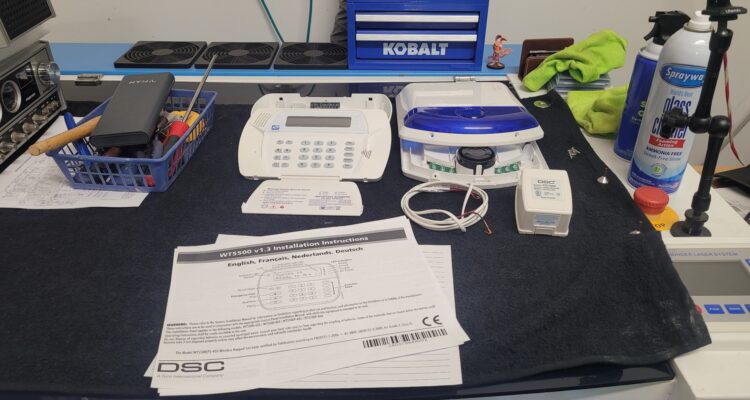
    When my family and I moved into our new house, we found a legacy DSC Alarm Panel and its suite of wireless sensors already installed. Since the system was outdated, unmonitored, and completely disconnected from modern alert systems, I opted to remove it. However, the hardware itself—a testament to its vintage engineering—was robust and still functional. I decided that instead of tossing it, I would transform this robust, inherited system. This multi-part series isn’t just about cleaning up an old alarm; it’s about transforming it into an off-grid, resilient, and intelligent security guardian using the Meshtastic mesh networking protocol! My ultimate goal is to create a fully self-reliant, peer-to-peer notification system that can alert me even when the internet is down, power is out, or cellular networks are jammed. I am taking this abandoned, time-tested wireless DSC system and giving it a powerful, modern, digital voice.

    President Dwight D. CB Base Resto-Mod Part 3

    🔬 Part 3: Documentation and Cleanup Complete – The Final Blueprint (This post directly follows the investigative findings detailed in President Dwight D. CB Base Resto-Mod Part 2.) This post marks a crucial phase transition! We executed the Initial Restoration (Cleaning) and the rigorous Technical Investigation (Data Collection) using the equivalent schematics. We now have the definitive blueprint showing the nature and intent of the modifications, but the final confirmation of function awaits the test bench in Part 4. The need for component replacement will be determined only after exhaustive initial performance tests. 1. 🧹 Step One: Initial Restoration and Deep Clean Before trusting our visual inspection or beginning the technical research, stabilization was necessary. This initial phase was purely physical cleaning—no components were removed, replaced, or adjusted. Deep Cleaning the Base Station Dust Removal: We used compressed air and soft brushes to carefully remove the thick, accumulated dust and grime from the main PCB, heat sinks, and chassis interior. This simple act drastically improved component visibility. Chassis and Controls: The exterior chassis, faceplate, and knobs received a thorough wipe-down with mild cleaners. Results: The cleaning was a success! We now have clear sight lines across the entire board, making the wiring easier to trace.   2. 📖 Step Two: Technical Investigation and Functional Analysis 🗺️ Using documentation for the equivalent PC-198AB chassis, we performed a side-by-side analysis of the schematics against the physical wiring. This gave us the necessary insight to understand the function and purpose of the mods, which we will now validate with testing. The Cobra 29XLR used 2 boards. The main one was a PC-198AA and the other was a PC-241AB 1/2. Looks like most of the docs for the XL29 with PC-198AA. This should give us some clarity. Cobra 29XLR Owner Manual Cobra 29XLR OEM Schematic Cobra 29XLR SVC MAN Schematic Cobra 29XLR Service Manual The Four Highly Probable Modifications We Now Identify: Mod # Hypothesis Purpose & Next Step (Validation) A Frequency Expansion PURPOSE CONFIRMED: Wiring alters the PLL’s BCD pins for extended channel selection. VALIDATION: Part 4 will confirm if the bands are stable and correctly programmed. B Clarifier Track PURPOSE CONFIRMED: The disc capacitors stabilize the TX/RX frequency track in the VCO circuit. VALIDATION: Part 4 will test if the transmit frequency follows the receive frequency across the sweep. C Variable Power PURPOSE CONFIRMED: Wiring intercepts the Automatic Power Control (APC) circuit. VALIDATION: Part 4 will confirm if the repurposed knob controls RF output power. D Audio/Modulation Tweak PURPOSE CONFIRMED: Wires/soldering in the AMC circuit suggest the limiter is bypassed. VALIDATION: Part 4 will measure the modulation percentage to confirm if it swings beyond stock limits. The Repurposed Switch Solved! We successfully traced the wires for the Channel Expansion mod (Mod A) and found they lead to the Noise Blanker (NB) switch. We now know which factory function was sacrificed, ready for functional testing. 3. 🎬 What’s Next: The Testing Phase The investigation is complete, and we have the full restoration blueprint. Now, we prepare for the physical work and the critical validation step. Part 4 will involve the rigorous performance testing of the currently configured radio, after replacing the failing peripherals (cords, jack). This testing will be the final step to CONFIRM the functionality of all four mods. The decision to install newer components, remove mods, or keep the rig “as is” will be made only after testing reveals a failure or performance shortfall. We are sticking to the mantra: Document, Test, and Only Then Decide to Replace.

    President Dwight D. CB Base Resto-Mod Part 2

    🔬 Part 2: Cracking the Case – Board ID, PLL, and Hidden Mods! You can find President Dwight D. CB Base Resto-Mod Part 1 here. The moment of truth arrived! I cracked open the President Dwight D. base station, ready to confirm the board type and uncover the history hidden beneath its metal shell. This radio had clearly seen some enthusiastic use—and definitely some meticulous user-installed modifications. 1. Board ID: Confirmed PC-198AB Chassis The first priority was identification. I quickly confirmed the board version: it’s the classic PC-198AB chassis, distinguished by its use of the well-known Uniden D858 PLL chip! This chip and board combination immediately told me something important: this specific rig was from the era of radios highly favored by enthusiasts for modifications. 2. A Modder’s History: Three Core Findings This radio was definitely not stock! The moment the lid came off, it was clear a previous owner had a serious interest in getting more performance and functionality out of the rig. I found evidence of three major, non-factory interventions: Mod A: Channel Expansion (The PLL Wiring) 📈 This is the most visually obvious and complex modification. It dramatically extends the radio’s frequency capability. Evidence: Multiple colored wires (green, blue, yellow, and brown) are soldered to the pins of the D858 PLL chip, and a large resistor bridges two adjacent points. Hypothesis: This is the classic technique used to alter the PLL’s digital programming code, enabling the radio to access expanded channels (often referred to as “upper” and “lower” bands) outside of the standard 40 CB channels. Next Step: I strongly suspect those two green wires visible near the PLL are running to the front panel, having repurposed the Noise Blanker and or CB/PA switches to control the band switching. Tracing this will be critical in Part 3! Mod B: Unlocked Clarifier (TX/RX Track) – Capacitor Tweak 🔗 Flipping the board over revealed a precise adjustment made near the frequency control circuits. Evidence: Two distinct disc capacitors (identifiable by their shape and insulation) are hand-soldered across two points on the foil side of the board in the Clarifier (Delta Tune) circuit area. These are user-installed components, not factory parts. Hypothesis: This setup enables the Clarifier Unlocked (TX/RX Track) feature. The capacitors are strategically placed to tailor the frequency response of the Voltage Controlled Oscillator (VCO), ensuring the transmit frequency tracks the receive frequency consistently as the Clarifier knob is adjusted. This is a crucial mod for talking to others on those expanded channels. Mod C: Modulation/Audio Circuit Tweak 🔊 More non-factory wiring was found near the rear of the board, suggesting a focus on audio performance. Evidence: Several additional, loose wires (red, white, and black) are hand-soldered to the foil side of the board in the area where the main factory harness connects. This spot is typically near the Automatic Modulation Control (AMC) and audio circuits. Hypothesis: This is likely an attempt to enhance the modulation (make the audio louder/punchier) by tweaking the gain or modifying the modulation limiter to achieve greater swing on the air. 🎬 What’s Next: The Road Ahead The President Dwight D. is turning out to be a fascinating piece of radio history! It was clearly a highly customized workhorse. My next steps for Part 3 will be to clean up the unit and dust it all off and tidy it all up after a close visual inspection. Then verify reference service manuals, diagrams, schematics, etc… to officially confirm the switch repurposing, and to clarify which suspected mods are in fact mods or repairs. I will decide later which of these modifications to preserve or remove in the interest of stability and clean performance, check and replace any suspect caps, and/or begin the critical restoration of the classic Astatic D-104 TUP9 microphone. For now I’m going to get it all figured out and working. More to follow! Here are more pics:

    President Dwight D. CB Base Resto-Mod Part 1

    🎙️ Resurrection of a Classic: President Dwight D. CB Base & Astatic D-104 TUP9 Resto-Mod! Stoked to finally crack open my President Dwight D. CB Base Station! This rig, a decade-long resident of the garage, fired right up a few years ago and was technically working. Now it’s time for a proper restoration and revitalization to ensure this classic rig lasts! My plan focuses on preservation, performance, and a critical deep-dive into its legendary companion, the Astatic D-104 Power Mic on the TUP9 stand. 🔎 Phase 1: Internal Inspection & Component Audit Before replacing any parts, I need to know the radio’s precise configuration and history of modifications. This is crucial for future component sourcing and tuning. Board Identification: The President Dwight D. came with two main boards. I’ll open it up to identify the Phase-Locked Loop (PLL) chip: PC198AA Board: Uses the AN-858-PLA U PD858 PLL. PC 407 Board: Uses the U PD2816 PLL. Modifications Check: I’ll be looking for any evidence of “Super Mods,” specifically if the clarifier has been clipped or if any modulation tuning has been performed. Capacitor & Resistor Inspection: I’m taking the “don’t fix it if it ain’t broke” approach with a major exception: vintage electrolytic capacitors degrade over time. I’ll be inspecting and selectively replacing these key components for long-term stability and optimal audio coupling. 🎤 Phase 2: The Astatic D-104 TUP9 Resto-Mod The Astatic D-104 on a TUP9 base is an iconic combination that deserves the full restoration treatment. 1. Cleaning and Maintenance Deep Clean: A thorough cleaning of the mic head, chrome, and the heavy TUP9 base to remove years of dust and grime. Contact Cleaning: The Push-To-Talk (PTT) bar mechanism and the volume potentiometers (pots) inside the TUP9 stand will be cleaned with high-quality contact cleaner (like DeoxIT). This is essential to eliminate static, scratchy audio, and intermittent keying. 2. Cord Replacement & Wiring The old microphone cord will be replaced with a new, high-quality cable. Crucial Step: The new cord must be correctly wired to mate the D-104 (Audio, Ground, TX/PTT, RX) with the President Dwight D.’s mic jack (in this case a 4 pin GX16 aviation connector). Getting the pinout right is essential for it to key up and transmit audio properly! 3. Performance Upgrades (“Resto-Mod” IF required) Amplifier Board Upgrade: The internal pre-amp board in the TUP9 is a common point of failure or weak performance. I may replace the vintage board with a modern, low-noise amplifier kit tailored for the TUP9 base to provide cleaner, more punchy modulation. RF Filtering: D-104s are notorious for picking up stray RF (Radio Frequency) energy. I will check for and potentially install a small, simple RF suppression network (capacitor/resistor) on the audio line to keep the signal clean. 🛠️ Phase 3: Final Tune-Up & Reassembly With the internal components secured and the D-104 revitalized, the final steps will bring the entire base station back to peak condition. Task Detail Pots & Switches Clean all remaining potentiometers and switches in the radio (RF gain, volume, squelch, channel selector). Cord Replacement Replace the old, stiff power cord (not just the mic cord!) for safety and a fresh feel. Alignment I will check the radio’s frequency and perform a basic tune-up and alignment to maximize its transmitted power and receive sensitivity, ensuring it’s right on-frequency. Wish me luck on this fantastic project! I’ll be posting updates on the board type, any mods I find, and the transformation of this classic rig!  You can find President Dwight D. CB Base Resto-Mod Part 2 HERE.

    Intermittent Charging System Anomaly on a 2011 Kia Sedona EX – SOLVED

    This technical case study details the advanced diagnosis of a persistent, intermittent charging system failure and stalling anomaly on a 2011 Kia Sedona EX (3.5L V6). After multiple failed alternator and battery replacements, the focus shifts to finding elusive high-resistance faults in terminations, grounds, and control relays. The guide outlines a precise diagnostic strategy utilizing Thermal Imaging (TI) and specialized electrical testing to pinpoint the true cause of the chronic electrical failure.

    Soltron Electronic PCB VR Replacement

    This ia a Soltron Electronic III Display PCB from an Ergoline Soltron Chill XL70 Tanning Bed. This board has obvious thermal defects to the L5973D voltage regulator IC as well as to the trace and the board. It is rumored that this particular board is plagued with this particular issue. The entire board new is likely $800~$1000 and used ones can go for $400~700.   Here is some imagery of the affected component:           These ICs are surface mount and are soldered on the underside. Without a decent hot air soldering station, flux, solder paste, etc… you could botch the repair. Since the original chip was toast anyway, i poured the heat to it with a touch of flux and removed it. It takes patience (as well magnification in my case) but it’s not too bad, you just have to be careful not to overheat any surrounding components, etc… Then i cleaned up the pads and traces (except for the one that was not a charred crevasse in the board), applied solder paste to the clean pads, then a touch of flux and the chip settled into place (after 5 solid minutes of nudging and shifting and heating). Once it was tacked into place a made sure i had good flow everywhere, then used a single strand of some 14~12 AWG stranded and made a good repair between the leg of the IC and the pad. Here is the 1st try. It probably would have been okay… but I reworked those areas. Here is it again after rework: This board will be field tested and I will update this as needed. UPDATE: That did not fix the board. Back to board-level diag… We will keep you posted.