Repair Procedures
REMOVAL
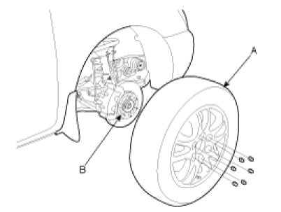
1. Raise the vehicle and remove the wheel & tire assembly (A) from the front hub assembly (B).
Tightening torque Nm (Kgf.m, lb-ft):
90 - 110 (9.0 - 11.0, 65 - 80)
2. Loosen the drain plug and drain the ATF.
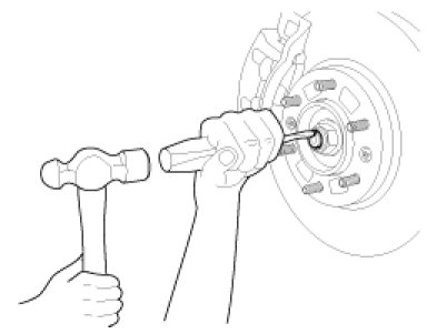
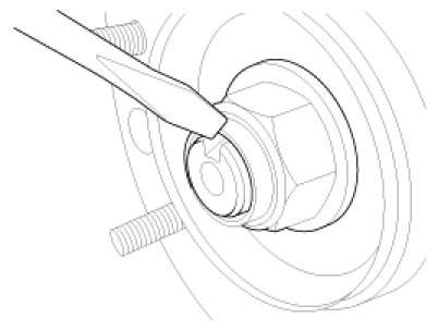
3. Unstake the driveshaft lock nut using a chisel and hammer.
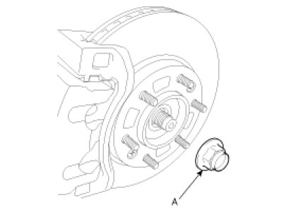
4. Remove the driveshaft lock nut (A).
Tightening torque Nm (Kgf.m, lb-ft):
245 - 275 (24.5 - 27.5, 177 - 199)
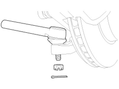
5. Remove the split pin and castle nut form the tie rod end ball joint.
Tightening torque Nm (Kgf.m, lb-ft):
60 - 80 (6.0 - 8.0, 43 - 58)
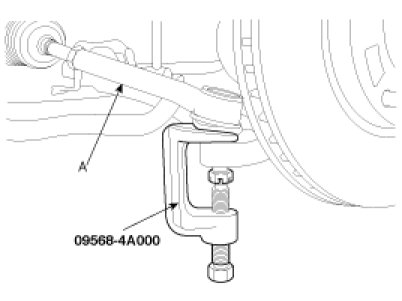
6. Disconnect the tie rod end (A) from the knuckle using a SST (09568-4A000).
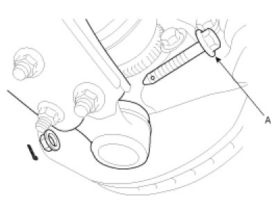
7. Remove the split pin and lower arm bolt and nut (A).
Tightening torque Nm (Kgf.m, lb-ft):
90 - 120 (9.0 - 12.0, 65 - 87)
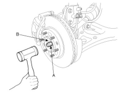
8. Using a plastic hammer, disconnect the driveshaft (A) from the front hub assembly (B).
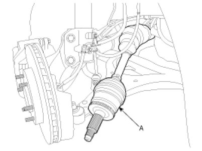
9. Removal of the driveshaft [RH].
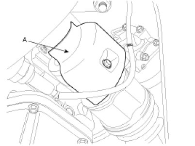
A. Remove the heat protector (A).
B. Remove the inner shaft bearing bracket assembly mounting bolts (A).
Tightening torque Nm (Kgf.m, lb-ft):
Gasoline: 50 - 65 (5.0 - 6.5, 36 - 47)

10. Insert pry bar (C) between the transaxle case (B) and driveshaft joint (A), separate driveshaft from the transaxle.
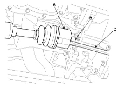
CAUTION:
- Use a pry bar being careful not to damage the transaxle and joint.
- Do not insert a pry bar too deep, as this may cause damage to the oil seal.
- Do not pry on the driveshaft by excessive force it may cause components inside the joint kit to dislodge resulting in a torn boot or a damaged bearing.
11. Pull out the driveshaft from the transaxle case.
CAUTION:
- Plug the hole of the transaxle case with the oil seal cap to prevent contamination.
- Replace the retainer ring whenever the driveshaft is removed from the transaxle case.
INSTALLATION
CAUTION:
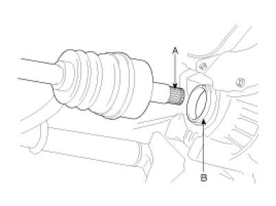
- Replace the circlip with new ones before the installation.
- Before the installation, apply the gear oil on the driveshaft splines (A) and contacting surface of differential case oil seal (B).
1. Installation is the reverse of removal.
CAUTION:
- After installing the driveshaft joint to the transaxle case, be sure not to come out.
- The driveshaft lock nut should be replaced with new ones.
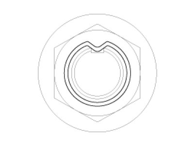
- After installation driveshaft lock nut, stake the lock nut using a chisel and hammer as shown in the illustration below.
INSPECTION
1. Check the driveshaft boots for damage and deterioration.
2. Check the ball joints for wear and damage.
3. Check the splines for wear and damage.

DISASSEMBLY
NOTE:
- Do not disassemble the BJ assembly.
- Special grease must be applied to the drive shaft joint. Do not substitute with another type of grease.
- The boot band should be replaced with a new one.
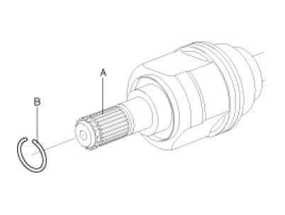
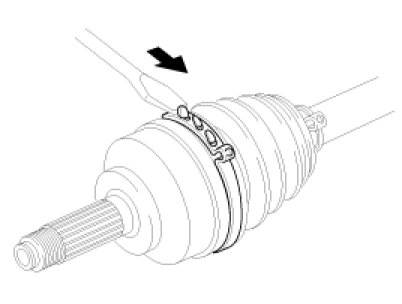
1. Remove the clip (B) from drive shaft splines (A) of the transaxle side.
2. Remove both boot bands from the transaxle side UTJ case.
3. Pull out the boot from the transaxle side joint(UTJ).
4. When separating the joint and boot (A), remove the grease from the UTJ case (B).
CAUTION:
- Be careful not to damage the boot.
- According to illustration below put alignment marks across spider roller assembly (A), UTJ case (B), and shaft splines (C) to aid in reassembly.
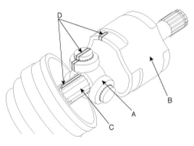
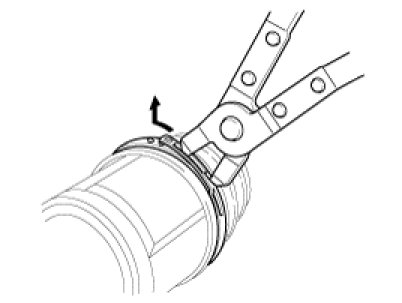
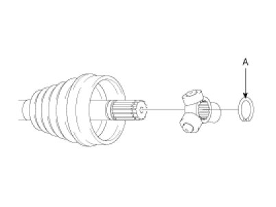
5. Using a plier or flat-tipped (-) screwdriver, remove the snap ring (A).
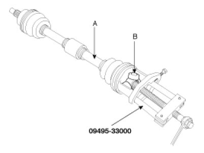
6. Remove the spider assembly (B) from drive shaft (A) by using the Special Tool(09495-33000).
7. Clean the spider assembly.
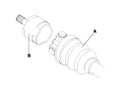
8. Remove the boot (A), of the transaxle side joint(UTJ).
CAUTION:
Wrap tape (B) around the driveshaft splines (C) to protect the boot (A).

9. Remove both bands on the side of wheel.
10. Pull out the joint(BJ) boot on the side of wheel into the transaxle direction.
CAUTION:
Be careful not to damage the boot.